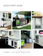
background image

USER GUIDE & SERVICE MANUAL

ADA 

 UACR014 

 14” Crescent Ice Maker

Summary of Contents for ADA UACR014

Page 1: ...USER GUIDE SERVICE MANUAL ADA UACR014 14 Crescent Ice Maker...

Page 2: ...er Hookup General Installation Grille Installation Door Swing Door Adjust Maintenance Cleaning Cleaning Condenser Extended Non Use Operating Instructions First Use Ice Airflow and Product Loading Serv...

Page 3: ...lect products are available worldwide PRODUCT INFORMATION Looking for additional information on your product User Guides Spec Sheets CAD Drawings Compliance Documentation and Product Warranty informat...

Page 4: ...or moderate personal injury property or equipment damage This unit contains R600a Isobutane which is a flammable hydrocarbon It is safe for regular use Do not use sharp objects to expedite defrosting...

Page 5: ...n place so children may not easily climb inside If the unit is being removed from service for disposal check and obey all federal state and local regulations regarding the disposal and recycling of re...

Page 6: ...mperatures may reduce the unit s ability to reach low temperatures and or reduce ice production on applicable models For best performance keep the unit out of direct sunlight and away from heat genera...

Page 7: ...he unit Always keep your working area dry NOTICE Electrical installation must observe all state and local codes This unit requires connection to a grounded three prong polarized receptacle that has be...

Page 8: ...ufficient if door protrudes beyond adjacent cabinetry PRODUCT DIMENSIONS REAR FRONT TOP SIDE Typical Counter Height 34 1 8 870 mm to 35 1 8 892 mm Cutout Height 24 7 8 632 mm Filler Panel Not Provided...

Page 9: ...only Do not use any plastic water supply line The line is under pressure at all times Plastic may crack or rupture with age and cause damage to your home Do not use tape or joint compound when attachi...

Page 10: ...evenly Use a level to confirm the unit is level Level should be placed along top edge and side edge as shown INSTALLATION 1 Plug in the power electrical cord 2 Gently push the unit into position Be c...

Page 11: ...touch the condenser fins The condenser fins are SHARP and can be easily damaged Removing the grille 1 Disconnect power to the unit 2 Open unit door 3 Remove the center screw 4 Remove grille by sliding...

Page 12: ...ndle if installed next to a wall If installing a handle on an integrated panel be sure to allow for the necessary clearance 16 1 2 90 Door Swing Stainless Steel 16 1 2 90 Door Swing Black White and Wo...

Page 13: ...it desirable to mount the door on the opposite side of the cabinet The hinge hardware will be removed and reinstalled on the opposite side of the cabinet Remove arrow clips 1 With a puddy knife or ot...

Page 14: ...e pivot screw in the same hole from the opposite surface 2 Lift the door rotate 1800 and set door onto the bottom hinge 3 Align edge of top hinge with the outer edge of the unit 4 Install hinge onto t...

Page 15: ...U Line recommends discarding the ice produced during the first two to three hours of operation to avoid possible dirt or scale that may dislodge from the water line To turn the unit on or off Press th...

Page 16: ...s operation You may hear the compressor or fan motor the water valve or ice dropping into the ice bucket CAUTION NEVER use an ice pick knife or other sharp instrument to separate cubes Shake the ice b...

Page 17: ...ge of an adjustment to the screw can cause the water to overflow the ice maker and can cause property damage 3 Turn the adjusting screw toward the minus sign clockwise for smaller cubes or toward the...

Page 18: ...NTEGRATION OPERATING INSTRUCTIONS MAINTENANCE SERVICE Airflow and Product Loading NOTICE The unit requires proper airflow to perform at its highest efficiency Do not block the front grille at any time...

Page 19: ...non chlorine glass cleaner Do not use cleaners not specifically intended for stainless steel on stainless surfaces this includes glass tile and counter cleaners If any surface discoloring or rusting a...

Page 20: ...discard ice 3 Place towel or other absorbent material on bottom of ice bin 4 Fill the ice bucket half full with warm not hot water This will help the unit defrost faster 5 Place the ice bucket back i...

Page 21: ...nvironmental conditions more or less frequent cleaning may be necessary WARNING Disconnect electric power to the unit before cleaning the condenser NOTICE DO NOT use any type of cleaner on the condens...

Page 22: ...n the evaporator allow ice to thaw naturally 4 Clean and dry the interior of the unit Ensure all water has been removed from the unit 5 The door must remain open to prevent formation of mold and milde...

Page 23: ...ency to reflect normal appliance operating noises Listed below are common refrigeration components with a brief description of the normal operating sounds they make NOTE Your product may not contain a...

Page 24: ...setting Ambient temperature where installed Installation in direct sunlight or near a heat source The number of door drawer openings and the time the door drawer is open The time the internal light is...

Page 25: ...GHT BLUE WHITE DARK BLUE BLACK BROWN BLACK BROWN WHITE DARK BLUE BIN SW NO NC C WATER SW NC NO C H O L D S W N O N C C CAM 3 RPM MOTOR LIMIT SW MOLD HEATER YELLOW BLACK RED WHITE WHITE DARK BLUE BROWN...

Page 26: ...nt of a part the servicer is authorized to replace the part in question The part that caused the damage must be returned to U Line in its entirety The part must be clearly labeled with the serial numb...

Page 27: ...shes 12 represents the production month In most cases warranty status can be verified by the production date information within the serial number Alternatively a Proof of Purchase or equivalent may su...

Page 28: ...0 10 Drier 80 54055 00 11 Evap cabinet assembly 80 54623 00 12 Gasket door 80 54619 00 13 Grille w screws 80 54622 00 14 Handle w screws 80 54621 00 15 Hinges 2 w screws 80 54592 00 16 Ice bucket 80 5...

Page 29: ...s will be shipped at no charge after U Line confirms warranty status Please provide the model serial number part number and part description Some parts will require color or voltage information If U L...

Page 30: ...Lower than normal Warm near room temperature Hot Warm Warm Extremely cold near inlet Outlet below room temperature Lower than normal Partial Restriction Somewhat lower than normal vacuum Warm near ro...

Page 31: ...tatic wrist strap that is grounded to an electrical ground or grounded water pipe Handle circuit boards carefully and avoid touching components To measure the start winding resistance measure across t...

Page 32: ...ce Bin switch inoperable closed Replace bin switch Bin arm binding Lubricate bin arm pivot points or loosen bin arm lever screw Water will not stop filling Water switch inoperable closed Replace water...

Page 33: ...fill tube assembly Defrost drain line not in drain pan Position drain line in drain pan Crack in water line Replace water line Water leak inside unit Ice maker assembly fill cup obstructed Remove obst...

Page 34: ...tage Voltage Drop Wiring Temperature Control Failure Water Adjustment Bin Switch Failure NO NO EVERYWHERE INTERMITTENT AT 3 00 YES NO AT 12 00 DOES THE UNIT HARVEST ICE IF THE EJECTOR BLADES ARE MOVED...

Page 35: ...2 and 3 are closed Power to the condenser Power to the condenser fan Figure 1 Freeze Cycle SWITCH LIMIT orange black black black MOTOR MAKER ICE MOLD HEATER WATER SWITCH FILL C NC MOTOR FAN LOAD OVER...

Page 36: ...power goes through bin arm switch to the ice maker motor If bin arm is up the ice maker will not harvest Figure 2 Harvest 1 Cycle Hold Switch in Normal Position SWITCH LIMIT orange black black black M...

Page 37: ...r motor and mold heater Ejector blades stall on ice and ice maker motor pulsates until mold heater warms and ice releases Figure 3 Harvest 2 Cycle Hold Switch in Switched Position SWITCH LIMIT orange...

Page 38: ...T CYCLE Ejector blades push ice into bucket and stop at 12 00 position Temperature control terminals 2 and 3 have closed during harvest cycle Next freeze cycle begins with power to the compressor and...

Page 39: ...rature After ice is sensed in the mold the 2 3 contacts open stopping the compressor and the 2 1 contacts are closed starting the ice maker motor The 2 3 contacts close 2 1 contacts open before the en...

Page 40: ...ch Open temperature 104 F Close temperature 83 F The function of this switch is to open in the event of an overheating condition This bi metal thermostat is normally closed and does not initiate the i...

Page 41: ...t tube 5 Remove front cover 3 6 Advance the ejector blade to the 3 o clock position by turning the 5 16 hex head on the small brass gear counterclockwise 4 7 Remove three screws from wall of freezer h...

Page 42: ...evaporator shelf 11 Apply 1 4 layer of fresh alumilastic to heater side of new ice maker 12 Replace parts in reverse order of removal 13 Reconnect all wires 14 Insert capillary tube into ice maker se...

Page 43: ...defrost unit remove ice bucket Turn unit off Use toweling inside to absorb water as it melts down This will help prevent water from getting onto customer s floor The defrost duration is dependent upo...

Page 44: ...d or other natural disasters The product must be installed operated and maintained in accordance with your product s User Guide The remedies described above for each warranty are the only ones that U...

Reviews: