5
Allegro
Preliminary 2/5/02
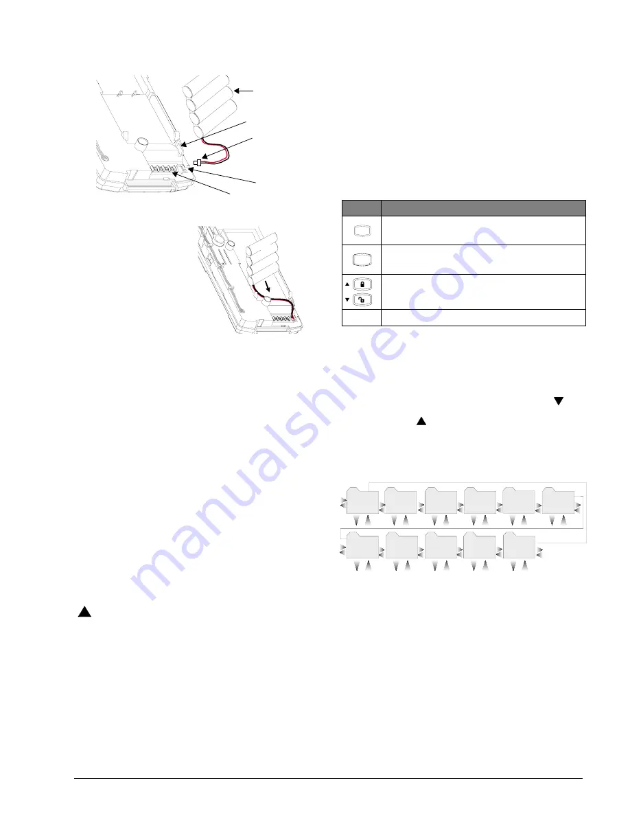
To connect the backup battery pack:
Figure 7. Connecting the Battery Pack
1.
Remove the panel hous-
ing from the back
mounting plate by lift-
ing the tab located on
the top of the panel and
pulling back.
2.
Slide the battery pack
into the space provided
on the back of the panel
(Figure 8).
Figure 8.Placement of Battery
3.
Plug the battery pack lead into the slot provided next to
the wire terminals (Figure 7).
Note
Be sure to run the battery pack wires below the battery and
thru the wire channel.
4.
Replace the panel housing into back mounting plate
and snap into place.
Note
See Appendix A: Troubleshooting on page 19 if the panel
displays
LOW
BATTERY
.
Powering Up the Panel
After connecting and wiring all devices to the panel, you are
ready to apply AC power to the panel.
To power up the panel:
Plug the transformer into an outlet that is not controlled
by a switch or ground fault circuit interrupt (GFCI). Be
sure to screw the top of the transformer onto the outlet
so that doesn’t fall out of the outlet.
The message,
PANEL
POWERED
UP
, will be displayed
WARNING
!
Be careful when securing the transformer to an outlet with
a metal cover. Hold the cover tightly in place. You could
receive a serious shock if the metal outlet cover drops
down onto the prongs of the plug while you are securing
the transformer and cover to the outlet box.
Note
If the panel does not display anything, immediately unplug
the transformer and disconnect the backup battery. Refer
to the “Troubleshooting” (on page 19) section.
Programming the Panel
This section describes how to program all settings found in
programming mode. You can program the panel manually
using the panel keypad to program on site. Or, using the
ToolBox software, you can automatically program remotely
via a modem and phone line.
Panel Keypad Button Programming
Functions
In program mode, panel keypad buttons let you navigate to
all installer programming menus for configuring the system.
Table 1 describes the panel keypad button functions in pro-
gram mode.
Moving Through Program Mode Tiers
and Menus
There are three tiers of programming menus. Tier 1 menus
are accessible immediately after entering program mode.
In Figure 9 arrows pointing right represent pressing
to
advance forward through the menus. Arrows pointing left
represent pressing
to move through the menus in reverse
.
The arrows below the tier 1 menu represents pressing
ƒ
and
‚
buttons.
Figure 9. Tier 1 Programming Menus
To advance to tier 2 program menus press the up or down
arrow keys to scroll thru the tier 1 menus. When you find
the menu you want to make changes to press
ƒ
once. This
will take you to tier 2 program menus.
Installer Programing Menu Items
This section guides you through the installer programing
menu items as they appear in sequence with the exception
of clearing memory.
Entering Installer Programming Mode
Entering programming mode on site is done from the panel,
using an installer code. The default installer code is
8 6 6 0 g 4 6 a . d s f
Battery Pack
Battery Pack
Battery Pack
Location
Battery Slot
Wire Terminals
Lead
Wire Channel
Table 1: Button Functions
Button
Programming Function
Selects menu item or data entry. Toggles between
on and off whenever needed.
Deselects menu item or data entry (if pressed
before #).
Scroll through available options at the current
menu tier.
0 thru 9 Enter numeric values wherever needed.
#
B y p a s s
S e l e c t
B a c k
*
S t a t u s
T i m e r s
P h o n e s
D e v i c e s
D o w n l o a d e r
C o d e s
A c c o u n t
#
*
#
*
#
*
#
*
#
*
#
*
C l e a r
M e m o r y
E x i t - D L
R e p o r t s
S i r e n
O p t i o n s
#
*
#
*
#
*
#
*
#
*
T i e r 1 M e n u


