background image

14

To install removable disk drives in the disk drive bay:

1.


Open the disk drive bay door on the front of the base unit.  The key is in the parts box.

2.


Take the removable disk drives from their carton and place them on an antistatic surface.
Carefully open the antistatic bags and remove the drives.  Note the ID numbers on the drives.

3.


Extend the latching clips on one drive and align the rails on the side of the drive with the slot
guides in the rightmost slot (Drive 0).  The metal casing of the drive faces to the left.  If you
install the drive reversed, it will not connect to the system.

4.


With your thumb, push the drive at the center between the latching clips until it slides all the
way into the slot and firmly engages the connector.

5.


Close the latching clips to lock the drive in the slot.

6.


Repeat steps 3 through 6 to install each remaining removable disk drive.  Fill each slot,
moving to the left adjacent slot as you install each drive.  Do not leave empty slots between
drives.

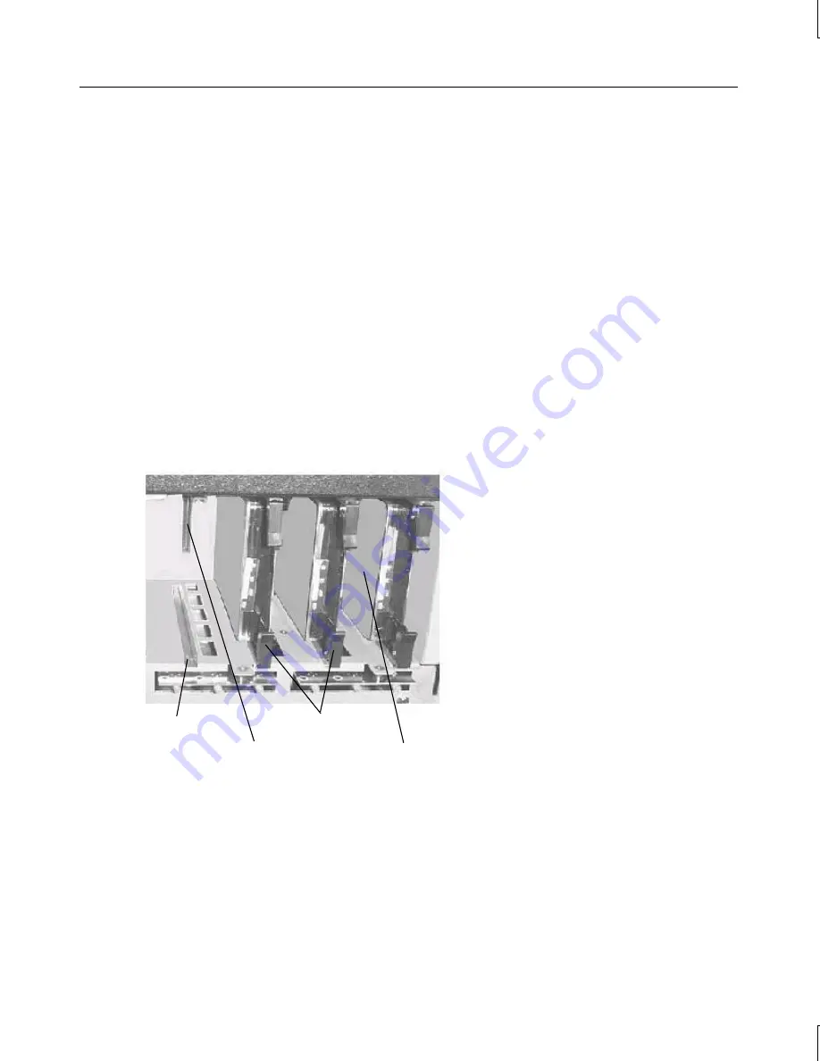
The following figure shows three removable disk drives installed in the disk drive bay.

Drive Rail

Drive Connector

Latching Clips

Drive 0

Connecting an External SCSI Device

You can add external single-ended Narrow Ultra SCSI drives to the system by connecting them to
the Narrow Ultra SCSI port on the back of the system.  The system features integrated Narrow
Ultra SCSI and Wide Ultra2 SCSI controllers.  However, only the Narrow Ultra SCSI controller
has an external port.  To connect external Wide Ultra or Wide Ultra2 peripheral devices, you must
install the appropriate SCSI controller as an expansion card.

Summary of Contents for StudioZ GT

Page 1: ...GT RAX Systems System Setup April 1999 D1AA00090 ...

Page 2: ...e equipment is operated in a residential installation This equipment generates uses and can radiate radio frequency energy If the equipment is not installed and used in accordance with the instructions it may cause harmful interference to radio communications However there is no guarantee that interference will not occur in a particular installation If this equipment does cause harmful interferenc...

Page 3: ...nsion Cards 12 Installing Removable Disk Drives 12 Connecting an External SCSI Device 14 Checking the System 16 Starting the System 16 What s Next 17 2 Setting Up the Software 19 Preparing for System Software Setup 20 Starting Operating System Setup 21 Finishing System Software Setup 23 Creating an Emergency Repair Disk 23 Creating System Software Backup Diskettes 24 Creating a QFE Update Software...

Page 4: ...ding Removable Disk Drive LEDs 42 Using InterSite Programs 43 Using Hardware Security Features 43 Finding Part and Serial Numbers 44 Cleaning the System 44 5 Configuring the BIOS 45 BIOS Overview 46 Starting BIOS Setup 46 Main Screen 47 System Time 47 System Date 47 Legacy Diskette A or B 48 Large Disk Access Mode 48 Keyboard Features 48 PS 2 Mouse 49 System Memory 49 Extended Memory 49 Memory Cac...

Page 5: ...60 6 Troubleshooting 61 Checking the System 62 System Power 62 System Boot 63 Video 65 Audio 66 Network 66 Peripheral Drive Errors 66 Miscellaneous Hardware 67 7 Reinstalling System Software 69 Before You Begin 70 System Software Products 70 Installing Windows NT Workstation 4 0 72 Configuring the Sound Driver 73 Updating the Operating System 74 Returned Goods Authorization RGA Form Warranty Proce...

Page 6: ...vi ...

Page 7: ...tures and provides other important basic information Chapter 5 Configuring the BIOS describes how to use the BIOS Setup program to configure the system s basic input output system BIOS Chapter 6 Troubleshooting describes how to resolve common system problems Chapter 7 Reinstalling System Software describes how to reinstall the operating system and associated system software if required Document Co...

Page 8: ... stress injuries when working with a computer Customer Support Intergraph Computer Systems offers an assortment of customer support options Hardware and Software Support Services Intergraph Computer Systems provides a variety of hardware services for Intergraph and third party equipment Services include warranty upgrades repair depot service on site hardware maintenance system administration and n...

Page 9: ...Web see the Software Support pages at http www intergraph com 3 At the login prompt key in your user ID or new if you have not used the IBBS before 4 Follow the menus to find what you need If you have trouble connecting to or using the IBBS call the Customer Response Center at 1 800 633 7248 product entry IBBS or leave a message for the IBBS System Operator at 1 256 730 1413 Telephone To get custo...

Page 10: ...A brief description of the question or problem More Support Options To get information on more customer support options Visit the Support pages on the World Wide Web at http www intergraph com ics For hardware support questions in the United States call 1 800 763 0242 For software support questions in the United States call 1 800 345 4856 Outside the United States contact your local Intergraph Com...

Page 11: ... delivered with the rack for instructions to unpack it and set it up Unpacking the System 2 Observing Safety Precautions 3 Placing the System Components 3 Understanding Vertical Units 4 Installing the Base Unit 4 Connecting the Cables 9 Installed Expansion Cards 12 Installing Removable Disk Drives 12 Connecting an External SCSI Device 14 Checking the System 16 Starting the System 16 What s Next 17...

Page 12: ...are CD ROM and diskettes and documentation Intergraph system software for Windows NT diskettes If you purchased a monitor from Intergraph Computer Systems its carton contains the following Monitor and power cord Video cable Monitor documentation NOTE If any of these items were not delivered call the Customer Response Center immediately at 1 800 633 7248 Save the packaging materials If you need to ...

Page 13: ...floor If the rack contains an AC distribution box or an uninterruptible power supply UPS do not connect the power cord to the wall outlet until instructed to do so in the system documentation Set up the system completely before you start it WARNING Once you install equipment into the rack do not move the rack with equipment installed or powered on or damage to internal components may result If you...

Page 14: ... 5 U or 8 75 inches of mounting space A vertical unit equals 1 75 inches and consists of three mounting holes The mounting hole diameter is 7 1 mm industry standard Mounting holes are counted upward after locating the first mounting hole within the range of vertical units required to install the equipment The following figure shows installing a tinnerman nut to mounting hole 3 of a vertical unit I...

Page 15: ...guides are not attached to the base unit do the following Remove the rail guides from the mounting rails The rail guide is the innermost sliding piece of the mounting rails and has a flexible tab at one end Attach the rail guides to the base unit using the flat head screws provided making sure the tab on the rail guide is towards the back of the base unit Refer to the following figure Flexible Tab...

Page 16: ... 75 inches of mounting space Choose the five vertical units you need and mark the fifth and sixth mounting holes starting at the bottom of the five vertical units Use a tape measure if you prefer that method of measurement 6 Use the flat head screws and bar nuts to secure the front rail teeth to the front of the rack With the flat side of the bar nut facing the screws loosely install two flat head...

Page 17: ...er to the following figure Tinnerman Nut Mounting Hole 8 Use the button head screws and bar nuts provided to secure the back rack rail teeth to the back of the rack With the flat side of the bar nut facing the screws loosely install two button head screws to the bar nut through the fifth and sixth mounting holes of the bottom 5 Us Slide the back rail teeth over the screws and tighten Ensure the ba...

Page 18: ...nit Slide the base unit into the rack rails until you hear a click Refer to the following figure 12 Press the locked rail tabs and slide the base unit completely back into the rack After the base unit slides back a few inches the base unit and rails slide together as a unit into the rack Refer to the following figure Rail Guide Each Side Locked Rail Tab Each Side Rack Rail Each Side 13 Install the...

Page 19: ...duced by the system NOTE While Intergraph Computer Systems recommends disconnecting the cables from the base unit before extending the base unit from the rack you can still extend the base unit without disconnecting the cables Be sure there is enough cable to allow the base unit to fully extend from the rack Use caution not to pinch the cables while extending or retracting the base unit The follow...

Page 20: ...l Serial Bus ports External Narrow Ultra SCSI devices Narrow Ultra SCSI port Network Ethernet port Speakers or headphones Audio Line Out port for on board audio controller not used if an audio controller card is in the expansion slots External audio device Audio Line In port for on board audio controller not used if an audio controller card is in the expansion slots Microphone Microphone port for ...

Page 21: ... is set to the proper line voltage for your location If your location uses 115 volts the number 115 must be visible If your location uses 230 volts the number 230 must be visible WARNING If you do not set the voltage selection switch correctly serious equipment damage may result when you turn on power to the system 7 Connect the system power cord to the AC receptacle on the base unit CAUTION When ...

Page 22: ... controller 2 PCI RAID controller or other expansion card 3 PCI Audio controller 4 PCI Fibre Channel host bus controller or other expansion card 5 PCI Fibre Channel host bus controller or other expansion card 6 PCI Fibre Channel host bus controller or other expansion card 7 Right PCI ISA Video processor For information on installing or connecting to expansion cards see the System Reference and the...

Page 23: ...S Wide Ultra2 SCSI controller controls the disks If your system is configured for RAID the disks are controlled by a single channel Mylex RAID controller expansion card Each removable disk drive has a label affixed to the front of the drive The left side of the label identifies the drive size in GB The label has blank spaces for the numbers to indicate the controller ADP the channel CH and the ide...

Page 24: ...the slot and firmly engages the connector 5 Close the latching clips to lock the drive in the slot 6 Repeat steps 3 through 6 to install each remaining removable disk drive Fill each slot moving to the left adjacent slot as you install each drive Do not leave empty slots between drives The following figure shows three removable disk drives installed in the disk drive bay Drive Rail Drive Connector...

Page 25: ... system and to each other CAUTION Make sure you shut down the system and unplug the power cord from the AC wall receptacle before connecting or disconnecting any peripherals including external SCSI devices NOTE Make sure the last device on a chain of external SCSI devices has an active SCSI terminator connected to the open SCSI port All other external SCSI devices must have SCSI termination disabl...

Page 26: ...om an AC distribution box or an uninterruptible power supply UPS is connected to the correct power outlet The base unit is retracted into the rack Starting the System WARNING If you start the system and then turn it off before completing the instructions in Chapter 2 Setting Up the Software you will have to reinstall the operating system and associated system software See What s Next for more info...

Page 27: ...l have to reinstall the operating system and associated system software Intergraph Computer Systems installs the operating system through Phase 1 of the Windows NT Setup process If you want to reload the operating system and system software instead of completing Phase 2 of Setup see Chapter 7 Reinstalling System Software For RAID systems the default RAID setup is disk drives striped to RAID level ...

Page 28: ...18 ...

Page 29: ...and associated system software for your GT RAX system Preparing for System Software Setup 20 Starting Operating System Setup 21 Finishing System Software Setup 23 Creating an Emergency Repair Disk 23 Creating System Software Backup Diskettes 24 Creating a QFE Update Software Diskette 24 What s Next 24 ...

Page 30: ...ory including depending on your system configuration graphics controllers audio controller video processor and other cards Core networking software and the NetBEUI protocol The latest certified Windows NT Service Pack software Quick Fix Engineering QFE software if needed InterSite software Intergraph Computer Systems installs the operating system through Phase I of the operating system Setup proce...

Page 31: ...es for your network s Domain Name System DNS servers IP addresses for your network s Windows Internet Name Service WINS servers The Windows NT delivery media contain software and drivers for both Reduced Instruction Set Computing RISC and Intel based systems When installing Windows NT software make sure you install it from the I386 directory on the delivery media Starting Operating System Setup WA...

Page 32: ... may want to learn more about system power startup and shutdown See Chapter 4 Operating Notes for this information To start the computer and set up the operating system software 1 Turn on the monitor by pressing its power switch 2 Press the Power button on the base unit The system starts and the EULA displays 3 Read the terms of the EULA and then follow the instructions displayed to complete the S...

Page 33: ...on the operating system desktop Double click this icon or go to Programs InterSite Welcome on the operating system Start menu to display InterSite Welcome InterSite Welcome helps you create a repair disk for the operating system and create backup diskettes of device driver software and other system software products You can use InterSite Welcome to get the latest driver and other system software f...

Page 34: ...n Manager does not list drivers or other system software products they are available on the operating system software CD ROM or on backup diskettes delivered with expansion cards See Version Manager Help for information on creating system software backup diskettes Visit the Intergraph Computer Systems site on the World Wide Web and vendor bulletin boards for new and updated drivers Creating a QFE ...

Page 35: ... Resolution 26 Changing the Default Video Display Driver 26 Correcting Video Display Problems 27 Configuring Audio 28 Configuring Networking 28 Configuring a Zip Jaz or Tape Drive 28 Configuring JBOD Disk Drives 29 Configuring RAID Disk Drives 29 Changing Drive Letters 30 Changing Virtual Memory Settings 31 Configuring the Symbios SCSI Controllers 32 Creating an Emergency Repair Disk 33 Getting Op...

Page 36: ...log see the operating system documentation and Help Resetting the Video Display Resolution If the monitor connected to your system does not support a resolution of 1024 x 768 you can reset the video display to another resolution To reset the video display resolution 1 Restart the system 2 At the boot screen select the VGA mode option and then log on to Windows NT 3 Right click the desktop and sele...

Page 37: ...the system in VGA mode 1 Power down and restart the system 2 At the boot screen select the VGA mode option After logging on to Windows NT in VGA mode check for the following common configuration problems and solutions A multi sync monitor is selected but a graphics display device with different video timings such as an Intergraph InterVue monitor is connected to the system Select the appropriate m...

Page 38: ...figure networking open Network in the Control Panel Follow the instructions in the dialogs to set up the system to use a network Be sure to set up the appropriate network protocols such as TCP IP for the network to which you are connecting the system After installing network protocols reinstall the appropriate Windows NT Service Pack software as recommended by Microsoft See the operating system do...

Page 39: ...configured to use RAID for redundant array of independent disks disk drives in the disk drive bay If so up to four removable RAID disk drives may be installed and are controlled by a single channel Mylex RAID controller The RAID controller provides RAID capabilities such as disk striping mirroring and redundancy for the removable disk drives The slots in the disk drive bay are numbered from 0 to 3...

Page 40: ...ocation in the disk drive bay shaded areas and how they are identified in Mylex BIOS and the Mylex RAID configuration utility Slot 4 Mylex ID Disk Label ADP 0 Slot 0 Slot 1 Slot 3 Slot 2 SCSI ID 4 SCSI ID 2 SCSI ID 1 SCSI ID 0 7JW KDQQHO 1XPEHU ADP 0 CH 0 ID 0 ADP 0 CH 0 ID 1 ADP 0 CH 0 ID 2 ADP 0 CH 0 ID 4 NOTE SCSI ID 3 is for an optional SCSI Activity Fault Tolerant Enclosure SAF TE card This S...

Page 41: ...r the following before changing page file settings The size of the page file If your system is equipped with a large amount of RAM Setup might create a page file that is unnecessarily large Drive letter reassignments If you reassigned your drive letters you may find it necessary to adjust your page file settings To change the size and location of the virtual memory page file 1 From Start click Set...

Page 42: ...ction Connecting an External SCSI Device in Chapter 1 If you connect non Ultra or non Wide Ultra2 SCSI external devices to the system NOTE Most SCSI adapters do not recognize a hard disk drive that was formatted using a different brand of adapter For example a hard disk drive formatted with an Adaptec SCSI adapter will not work with a Symbios SCSI adapter You must use only Symbios formatted hard d...

Page 43: ...TER 6 Select the appropriate rate Off 10 20 40 or 80 and press ENTER NOTE To select a rate of 80 the Width setting must be 16 If Width is set to 8 the maximum Sync Rate Megabytes sec is 40 7 Select Exit This Menu and then press ENTER 8 From the Device Selections menu select Exit This Menu and press ENTER 9 From the Utilities menu select Exit This Menu and press ENTER 10 Select Save Changes and pre...

Page 44: ...ase support You can get then from Microsoft s World Wide Web and FTP sites free of charge CAUTION If Intergraph Computer Systems provides a Service Pack through the IBBS or with a product it has been certified against Intergraph Computer Systems hardware as described in the announcement of its availability If you obtain a Service Pack from any other source be aware that it may not be certified aga...

Page 45: ... 36 Observing Operating Precautions 38 Booting the System from a CD ROM 38 Using the Keyboard 39 Using the Mouse 40 Using the Floppy Disk Drive 40 Using the CD ROM Drive 41 Understanding Removable Disk Drive LEDs 42 Using InterSite Programs 43 Using Hardware Security Features 43 Finding Part and Serial Numbers 44 Cleaning the System 44 ...

Page 46: ...Button Power LED Reset Button Disk Activity Light The power button is a momentary contact switch changing system states each time the button is pressed Use the power button to Start the system from a powered down state by pressing and releasing the Power button The system powers on and loads the operating system Power down the system by pressing and releasing the Power button after selecting the s...

Page 47: ...ct Windows NT and then press enter To log on to the operating system 1 If the logon dialog does not display press CTRL ALT DELETE to display it 2 Type a username and password into the appropriate boxes 3 If appropriate type a domain name 4 Select OK or press ENTER To log off restart shut down or power down the system 1 Go to Start Shut Down 2 To log off the operating system click Close all program...

Page 48: ...ter turning off power to the base unit wait at least 30 seconds before turning the power on again This allows the power supply to stabilize and the disk drives to stop spinning Booting the System from a CD ROM You can boot the system from a bootable CD ROM if needed However you cannot set the system s SCSI CD ROM drive to be the permanent boot device NOTE You cannot install Windows NT 4 0 by booti...

Page 49: ...NT SCRN Depending on the application in use prints the displayed screen to a printer SCROLL LOCK Prevents the screen from scrolling PAUSE Temporarily suspends screen scrolling or some operations CAPS LOCK Types all letters as capitals NUM LOCK Activates the numeric keypad CTRL Used with another key for application specific functions ALT Used with another key for application specific functions DELE...

Page 50: ...an find information on using it by right clicking the mouse icon in the taskbar tray or by going to Start Settings Control Panel Mouse and clicking Help in the toolbar Using the Floppy Disk Drive The system s floppy disk drive occupies a 3 5 inch external peripheral device bay and is accessible through a 3 5 inch slot on the front of the base unit The drive accepts standard 3 5 inch 720 KB and 1 4...

Page 51: ...the disc To insert a disc into a slot load CD ROM drive insert the disc printed side up into the slot To eject a disc from the CD ROM drive press the eject button adjacent to the CD ROM drive slot or tray If the software application being used prevents the disc from ejecting run the proper application command to eject the disc The media player application program s included with the operating syst...

Page 52: ...or RAID controller On a system with RAID disk drives an optional SAF TE card monitors the status of RAID disk drives The SAF TE card causes the left LED above each disk drive to indicate RAID disk drive status as follows Left LED Activity Disk Drive Status Off No error Steady on Disk drive rebuild stopped or disk drive is faulty Steady blink approx 1 per second Disk drive rebuild in progress Fast ...

Page 53: ...ctive management of computers InterSite SMART Disk Driver is a kernel level driver that supports self monitoring analysis and reporting technology SMART InterSite Diskeeper Lite helps you keep disk fragmentation to a minimum improving file creation and access times and system performance NOTE Hardware Monitor DMI Console and SMART Disk Driver are not delivered on StudioZ GT for SOFTIMAGE DS system...

Page 54: ...m How To Clean Mouse On the bottom of the mouse a retaining ring holds the tracking ball in place Remove the ring and turn the mouse over the tracking ball will fall out Blow gently into the opening Clean the tracking ball and rollers with a cotton swab and alcohol Replace the tracking ball and the retaining ring Keyboard Dust with a dry cloth Aerosol cleaners are commercially available to remove ...

Page 55: ...48 Keyboard Features 48 PS 2 Mouse 49 System Memory 49 Extended Memory 49 Memory Cache 49 Advanced Screen 50 Plug Play O S 50 Chipset Configuration 50 AGP Configuration 50 Memory Options 51 System Error Options 52 Parity Error Options 52 L2 Cache ECC Mode 53 INIT Upon Shutdown Cycle 53 PCI Configuration 53 I O Device Configuration 56 Boot 57 Floppy Check 57 Summary Screen 58 Boot Device Priority 5...

Page 56: ...ed by the user during the system s power on self test POST Starting BIOS Setup To start BIOS Setup 1 Restart the system When the system is started an Intergraph Computer Systems logo displays 2 Press the F2 key to start Phoenix BIOS Setup NOTE You can set a password to prevent unauthorized users from accessing BIOS Setup See Features Screen in this chapter While using BIOS Setup remember these tip...

Page 57: ...secondary master Disk access mode Keyboard features PS 2 mouse functionality System memory This section explains how to configure each of these parameters To move between the parameters use the up and down arrow and keys System Time To set the system time use TAB to move the prompt and select a field hours minutes or seconds Use the plus key to increase the number use the minus key to decrease the...

Page 58: ...perating systems require different settings If you are installing new software and the drive fails change the selection and retry NOTE Change this setting only prior to formatting the system disk Erratic system behavior or file corruption can occur if this setting is changed during normal system drive use Keyboard Features This parameter displays a submenu of options for configuring the features o...

Page 59: ...ccesses the cache Select this option and press enter to display the Memory Cache submenu Cache System BIOS Area This option controls caching of the system BIOS area The available settings are Write Protect or Uncached The default setting is Write Protect Cache Video BIOS Area This option controls caching of the video BIOS area The available settings are Write Protect or Uncached The default settin...

Page 60: ... is No NOTE This option should be set to No when using Windows 3 1 or Windows NT 4 0 Chipset Configuration This option displays a submenu of options for configuring the chipset features Press ENTER to display the submenu AGP Configuration This option displays a submenu of options for configuring the Advanced Graphics Port AGP features Press ENTER to display the submenu AGP Aperture Size Select the...

Page 61: ...he submenu ECC Mode When this option is enabled correction logic is used on data reads When disabled data reads from DRAM are supplied unaltered to the CPU bus The default setting is Disabled Single Cache ECC When this option is enabled default ECC operations are performed in one CPU bus clock 2 clocks are used when disabled Enhanced Page Hit Timing Enable this option to cause the chipset to drive...

Page 62: ...Address Parity Errors When this option is enabled a system error is generated when bad address parity is detected The default setting is Enabled Report Bad Received Data Parity When this option is enabled a system error is generated when parity errors are detected on CPU to PCI reads The default setting is Enabled Report Bad Transmit Data Parity When this option is enabled a system error is genera...

Page 63: ...menu with options for configuring IRQs for legacy ISA devices PCI Device Embedded SCSI A This option displays choices for configuring the features of embedded SCSI device A Entry Description Onboard LVD SCSI Controller Controls whether or not the system activates the embedded PCI device The default setting is Enabled Option ROM Scan Initializes device expansion ROM The default setting is Enabled E...

Page 64: ...s Use Auto only if no ISA legacy cards are installed The default setting is Auto select PCI Device Embedded NIC This option displays choices for configuring the features of the embedded Network Information Card NIC Entry Description Onboard Ethernet Controller Controls whether or not the system activates the embedded PCI device The default setting is Enabled Option ROM Scan Initializes device expa...

Page 65: ...ly if no ISA legacy cards are installed The default setting is Auto select AGP Device This option displays additional options for configuring the features of the AGP device Entry Description AGP Controller Controls whether or not the system activates the embedded PCI device The default setting is Enabled Option ROM Scan Initializes device expansion ROM The default setting is Enabled Enable Master ...

Page 66: ...default setting is Disabled ISA Graphics Device Installed A PCI device may require information on whether ISA graphics are installed on the system in order to enable the device to function correctly The default setting is No PCI PnP ISA UMB Region Exclusion This option reserves specific upper memory blocks for use by ISA devices Press the up or down arrow keys to highlight the memory block and the...

Page 67: ...nded Capabilities Port ECP or Enhanced Parallel Port EPP The default setting is Bi directional Floppy Disk Controller This option configures the operation of the floppy disk controller Select Disabled no configuration Enabled allows user configuration Auto to enable the BIOS or OS to set the configuration or OS Controlled displayed when the operating system controls the configuration The default s...

Page 68: ...d QuietBoot When disabled this selection displays the system diagnostics screen during boot up When enabled the system logo screen displays in place of the system diagnostics screen The default setting is Enabled Multiboot Use this option to display additional setup menus to configure system boot devices Press ENTER to display the multiboot submenu This submenu provides the following options Hard ...

Page 69: ...enabled the system requires a password upon starting up Either the Supervisor or User Password may be entered The default setting is Disabled Exit Screen When you are finished configuring the BIOS use the arrow keys to highlight the Exit option on the BIOS Setup main menu The Exit screen displays Choose one of the following exit options To move between the Exit options use the up and down arrow ke...

Page 70: ...diskette 5 Reboot your system with the MS DOS 6 X diskette in the floppy drive To make sure a clean DOS environment is loaded press the F5 key while the message Starting MS DOS is displayed After the system has restarted the cursor displays the A prompt 6 Now you can run the FLASHPROG utility from the bootable floppy disk Refer to the README TXT file included with the BIOS update for detailed inst...

Page 71: ...shooting Use this chapter to identify and resolve common basic system problems Checking the System 62 System Power 62 System Boot 63 Video 65 Audio 66 Network 66 Peripheral Drive Errors 66 Miscellaneous Hardware 67 ...

Page 72: ... See the Preface of this document for other information about contacting Intergraph Computer Systems When instructed to open the base unit see the System Reference delivered with the system for details on opening the base unit and working with internal components System Power Fails to power on Reason Solution Power cord not connected properly Verify that the power cord is properly connected to the...

Page 73: ...lace the DIMM s Timer Not Operational Memory failure in the first 64 KB or Timer 1 on the system board is not functioning Call the Customer Response Center Processor Error The CPU on the system board generated an error Call the Customer Response Center 8042 Gate A20 Failure The BIOS cannot switch to protected mode Call the Customer Response Center Processor Exception Interrupt The CPU generated an...

Page 74: ...able is not attached Ensure the floppy drive power cable is properly attached Floppy data cable is not attached Ensure the floppy data cable is properly attached to the floppy drive and to the system board System hard disk drive is not recognized Reason Solution Hard disk drive power cable not attached Open the base unit and ensure power cable is properly attached See the System Reference Hard dis...

Page 75: ...Faulty option board is installed in ISA slot Remove ISA board then restart the system See the System Reference Video System is powered on but screen remains blank Reason Solution Monitor not powered on Turn on power to the monitor Monitor power cord not connected Connect monitor power cord to AC outlet and monitor Video cable not properly installed Ensure video cable is connected to monitor and sy...

Page 76: ...tion If cable is properly connected notify your System Administrator Incorrect software configuration Notify your System Administrator Cannot plot to network printer or plotter on LAN Reason Solution Network cable disconnected Reconnect network cable ensure proper connection Printer or plotter not added to Print Manager on your system Notify your System Administrator Plot node does not recognize y...

Page 77: ...age during the system boot Replace the lithium battery on the system board One or more RAID controllers is not recognized Reason Solution Message displays Host adapter at baseport dc90h is not responding Remove the RAID controller and reinstall it into the same slot ensuring it is completely connected into the slot RAID controller firmware has been corrupted Call the Customer Response Center DMA b...

Page 78: ...68 ...

Page 79: ...erating system and associated system software on your GT RAX system Before you reinstall the software ensure that you read and understand this entire chapter Before You Begin 70 System Software Products 70 Installing Windows NT Workstation 4 0 72 Configuring the Sound Driver 73 Updating the Operating System 74 ...

Page 80: ...e backup diskettes of drivers or other system software products you can create them from the Intergraph System CD as described previously System software is also probably available on the operating system CD ROM or on backup diskettes or software CD ROMs delivered with expansion cards NOTE You must install certain drivers from backup or other diskettes The correct driver versions may not be on the...

Page 81: ...rk driver Version Manager and diskette ENSQ1371WNT4 Ensoniq 1371 audio driver Version Manager KEOPSDRV Merging Technologies Keops audio driver StudioZ GT CD SYMSCSI Symbios SCSI controller driver Version Manager SYMLVDSCSI Symbios LVDS SCSI driver Version Manager FC32_QHBA QLogic host bus adapter driver Version Manager MYLEXPCIDRV Mylex AcceleRAID 250 driver and utilities Version Manager TEWRTCH W...

Page 82: ...etup type select Custom Setup On a system with internal SCSI disk drives and a SCSI adapter press the S key to install the SCSI adapter driver from backup diskette Select Other Requires disk provided by a hardware manufacturer from the list and press ENTER Insert the diskette with the SCSI adapter driver into the floppy disk drive and then press ENTER Specify a driver for the CD ROM drive by press...

Page 83: ...pter 4 Operating Notes Do the following after you install Windows NT Service Pack software If you created a Quick Fix Engineering QFE_NT backup diskette from Version Manager during any previous initial system configuration install the QFE update software See the README TXT file on the QFE diskette for more information On a system with a Pentium III processor reinstall Intel s Streaming SIMD Extens...

Page 84: ...he Install Driver dialog box displays 5 Insert the Windows NT operating system installation CD in the CD ROM drive 6 Type DRVLIB MULTIMED JOYSTICK X86 in the Path text box and click OK The driver is installed 7 Restart the system Updating the Operating System Microsoft Service Packs and Service Releases contain the latest improvements and system fixes for Microsoft operating systems Service Packs ...

Page 85: ...aph Customer Response Center From Customer Name Customer Contact Phone Mail Address Reason for Return NOTE All returned equipment MUST be shipped in original Intergraph packaging to obtain warranty service WARNING Back up disk drives before returning equipment Intergraph is not responsible for data lost in shipping or repair process ...

Page 86: ...ystem you will be assigned a RGA log number 3 Complete the RGA Form on the previous page entering the RGA log number obtained from the Customer Response Center Ensure that the address in the From section is the location to which you want the equipment to be returned 4 Place the RGA form in the box containing the equipment This form must accompany returned equipment 5 Secure a Repair Depot address ...

Page 87: ...poration 9805 Kellner Road Huntsville AL 35894 TO Repair Depot RGA No ________________________ Intergraph Corporation 9805 Kellner Road Huntsville AL 35894 TO Repair Depot RGA No ________________________ Intergraph Corporation 9805 Kellner Road Huntsville AL 35894 ...

Page 88: ......

Reviews: