Interflex Datensysteme GmbH
4/13
6.4 I/O Expansion
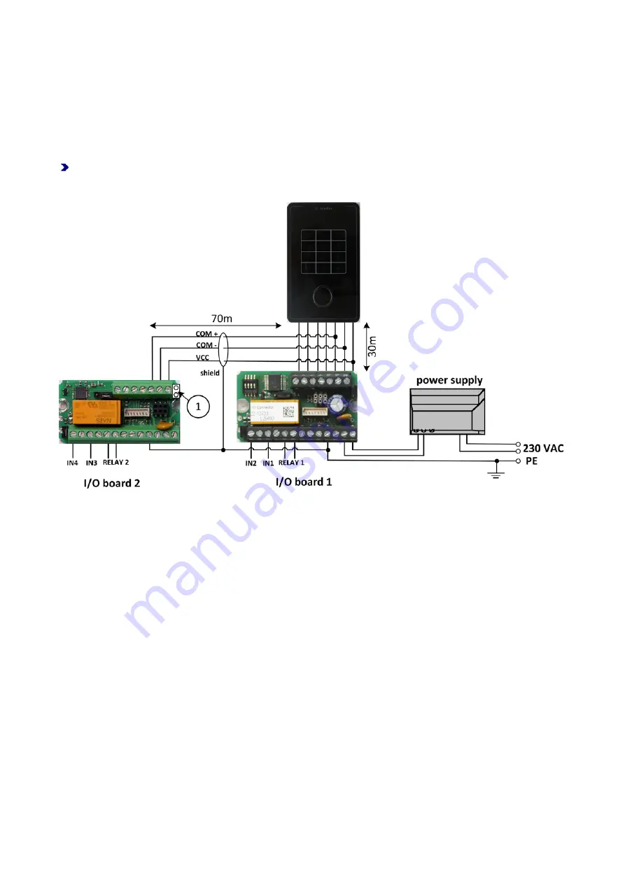
If more than 2 inputs or more than 1 relay is required, you can connect a second I/O controller board (order
no. 75-500-0141).
Please consider the following when planning a second I/O controller board:
For technical reasons, the length of the COM cable is limited to 100 m.
Reduce the length of the COM cable to ensure that a total length of 100 m is not exceeded.
Example:
The IF-80x terminal is connected to the I/O controller board 1 via a 30-meter-long cable. Then, the
cable for the connection to I/O controller board 2 may only have a length of 70 m.
In the example, bridge (1) on I/O controller board 2 must be removed.
6.5 Please Perform the Following Steps in the Specified Order
1. Strip approx. 8 cm of the data cable.
2. Wrap the drain wire (6) around the end of the insulation of the data cable.
3. Feed the connection cable through the strain relief.
4. Install the strain relief in such a way that the end of the insulation with the drain wire is electrically
connected to the back panel of the housing (10).
5. Clamp the blue wire under a nut of the strain relief (12).
6. Now, connect all of the cables coming from the I/O controller board to the terminal strip of the IF-800
Outdoor/IF-801 terminal.
7. Then, connect the blue wire from the back panel of the housing to the PE terminal.
8. Connect the terminal strip to the IF-800 Outdoor/IF-801 terminal.
9. Attach the IF-800 Outdoor/IF-801 terminal to the top and press it down until it rests against the wall.
10. Screw down the IF-800 Outdoor/IF-801 terminal on the bottom left side (11) using the M2x6 countersunk
screw included in the delivery.
11. Insert the mortise lock on the bottom right side and lock the IF-800 Outdoor/IF-801 terminal (13).
12. Use the enclosed plastic strips to seal the mortise lock.


