TELEPHONE PAGING
4
TP-6231
Equipment Set-up and Check List
Equipment Set-up and Check List
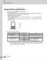
1. Make sure system is turned off before configuring the set-up.
2. PD-6359 REMOTE CONTROL
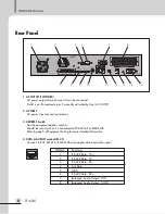
If remote control of PD-6359 is required, connect the power remote terminal of the TP-6231 (Terminal 5
on rear diagram of TP-6231) to the remote terminal of PD-6359.
3. Telephone line connection (2 configurations).
- 2 WIRE TELEPHONE INTERFACE
Connect a standard telephone (RJ11) line wire to the TP-6231(Terminal 13 on rear diagram of TP-6231)
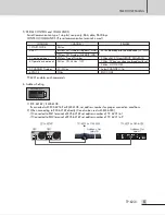
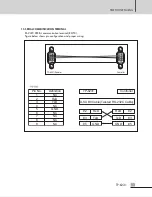
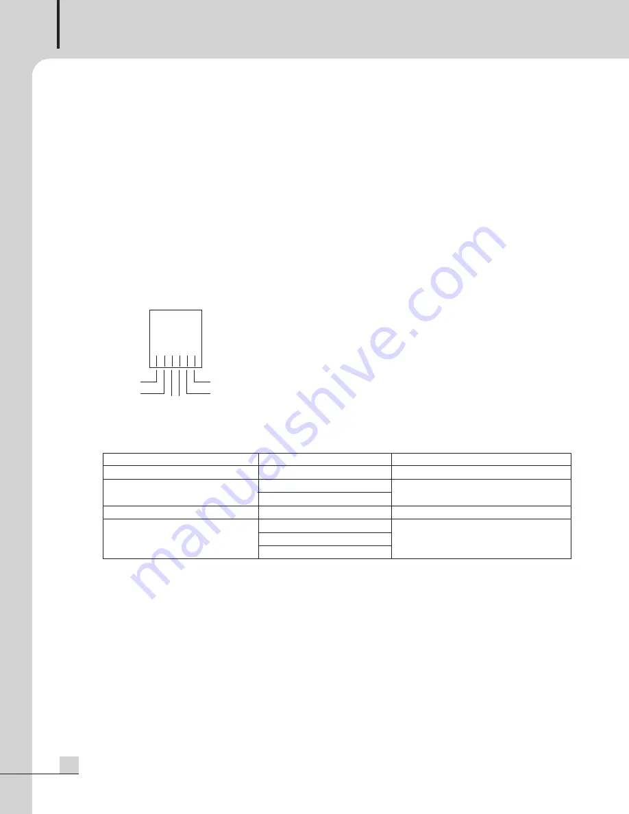
- 4 WIRE (2W E&M)
Refer to figure below for connector pin assignment. Used if you want to install a 2W E&M where private
exchange is installed.
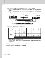
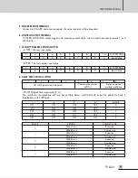
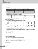
4. Broadcast Management Dial CODE
Telephone broadcasting Dial Codes. (Based on dial buttons)
※
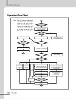
Note: When the paging broadcasting must be finish an asterisk (*), please exit by pressing the button. An
asterisk (*) If you do not press the broadcast button and you can not finish properly. In this case, the
power switch OFF then ON if it is restored.
①
⑥
⑤
②
③ ④
TELEPHONE
INTERFACE
① MOUTH
② GND
③ RING
④ TIP
⑤ EAR
⑥ -48V
TYPE
Broadcasting
Group Zone Broadcasting
Normal Broadcasting
Additional Functions
CODE
✽
7 7 #
✽
7 0 #
✽
7 1 #
✽
? ? #
✽
#
✽
#
✽
8 8 #
✽
9 9 #
REMARK
ALL Broadcasting
✽
70# : 01~08 Local ALL Broadcasting
✽
71# : 09~16 Local ALL Broadcasting
✽
??# : Select one from C01 to 16
✽
# # : Recording function
✽
88# : Switch to user mode
✽
99# : Release user mode


