


Indoor Dry Bulb Temperature(F)
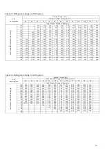
Heating Charge Chart
Outdoor Ambient Temperature(F)
Cooling Charge Chart
19
55
60
65
70
75
80
85
90
95
100
105
110
115
8
0
5
2
8
4
6
5
4
2
3
4
7
0
4
6
8
3
5
6
3
2
5
3
8
3
3
3
2
3
8
0
3
5
6
1
3
0
5
8
7
4
2
5
4
8
2
4
3
0
4
2
8
3
1
6
3
8
4
3
4
3
3
9
1
3
4
0
3
1
6
1
9
9
4
3
7
4
7
4
4
3
2
4
9
9
3
8
7
3
7
5
3
4
4
3
0
3
3
5
1
3
0
0
3
7
5
1
153
281
296
311
326
340
353
374
395
419
443
469
495
149
277
292
307
322
336
349
370
391
415
439
465
490
145
273
288
303
318
332
345
367
388
412
435
461
487
141
248
269
284
299
314
328
341
363
385
408
431
457
482
137
243
265
280
295
310
325
339
360
381
405
428
458
488
133
238
261
276
291
306
321
336
357
378
402
425
450
474
129
233
257
272
287
302
318
334
355
375
399
422
448
473
125
228
253
268
283
298
314
330
352
373
396
419
444
469
121
223
249
264
279
294
310
326
348
370
393
416
441
465
117
218
245
260
275
290
306
322
345
367
390
413
437
461
113
213
241
256
271
286
302
318
341
364
387
410
434
457
109
208
237
252
267
282
298
314
338
361
384
407
430
453
105
203
233
248
263
278
294
310
334
358
381
404
427
449
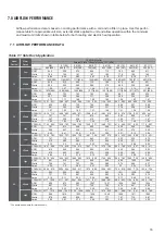
36K
Cooling Mode
60
62
64
66
68
70
72
74
76
78
80
82
135 336
347
358
369
380
392
399
406
413
420
424
432
128 328
339
350
361
372
384
390
396
402
408
413
421
121 320
331
342
353
364
376
381
386
391
396
402
410
114 313
324
335
346
351
358
363
370
377
384
391
399
107 305
313
321
329
337
345
352
359
366
373
380
388
100 295
303
311
319
327
335
342
349
356
363
369
377
93 286
294
301
309
316
323
330
337
344
351
358
366
86 277
284
291
298
305
312
319
326
333
340
347
355
79 267
274
280
287
294
300
307
314
321
328
336
344
72 258
265
271
277
283
289
296
303
311
318
326
334
65 248
254
260
266
272
278
285
293
300
307
315
323
3
1
3
5
0
3
7
9
2
0
9
2
3
8
2
5
7
2
8
6
2
0
6
2
8
5
2
0
3
4
9
2
7
8
2
0
8
2
3
7
2
6
6
2
9
5
2
1
5
2
9
2
4
8
2
7
7
2
0
7
2
3
6
2
6
5
2
4
4
7
8
2
9
7
2
2
7
2
5
6
2
8
5
2
7
3
30
36K
Heating Mode
Table 7-5 Refrigerant charge for H/P system
Table 7-6 Refrigerant charge for H/P system
High Pressure Detected Valve(psig)
High Pressure Detected Valve(psig)
Low
Pr
ess
ure
D
etecte
d Va
lve(p
si
g)
Low
P
ressure
De
tec
ted
V
al
ve(psig
)


