intensity IPRC2414KC-3 Installation Instructions Manual Download Page 16

16 

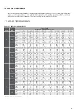
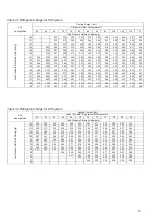
7.0 AIRFLOW PERFORMANCE

Airflow performance data is based on cooling performance with a coil and no filter in place. Use this perfor-
mance table for appropriate unit size, external static applied to unit and allow operation within the minimum 
and maximum limits shown in table below for both cooling and electric heat operation.  

7.1  AIRFLOW PERFORMANCE DATA 

Table 7-1 Side Duct Application 

0[0] 0.1[.02] 

0.2[.05] 

0.3[.07] 

0.4[.10] 0.5[.12] 0.6[.15]  0.7[.17] 

CFM(L/S) 
RPM 
Watts 
Amps 
CFM(L/S) 
RPM 
Watts 
Amps 
CFM(L/S) 
RPM 
Watts 
Amps 
CFM(L/S) 

1341 

〔 

633 

〕 

1286 

〔 

607 

〕 

1242 

〔 

586 

〕 

1193 

〔 

563 

〕 

1134 

〔 

535 

〕 

1063 

〔 

502 

895 

〔 

425 

〕 

775 

〔 

366 

〕 

RPM 630 

676 

720 

764 809 

854 

927 

960 

Watts 361 355 

348 340 331 

319 

298 284 

Amps 1.57 1.55 

1.52 1.51 1.46 

1.41 

1.34 1.29 

CFM(L/S) 

1510 

〔 

713 

〕 

1468 

〔 

693 

〕 

1420 

〔 

671 

〕 

1369 

〔 

647 

〕 

1292 

〔 

610 

〕 

1218 

〔 

575 

1128 

〔 

533 

934 

〔 

441 

〕 

RPM 701 

741 

779 

814 854 

892 

928 

987 

Watts 447 438 

428 419 408 

394 

377 347 

Amps 1.95 1.92 

1.88 1.84 1.8 1.75 

1.69 1.59 

CFM(L/S) 

1705 

〔 

805 

〕 

1658 

〔 

783 

〕 

1604 

〔 

758 

〕 

1549 

〔 

731 

〕 

1489 

〔 

703 

〕 

1416 

〔 

669 

1321 

〔 

624 

1179 

〔 

557 

〕 

RPM 781 

815 

849 

880 908 

938 

969 

1006 

Watts 558 547 

536 524 511 

493 

474 445 

Amps 2.45 2.41 

2.36 2.32 2.26 

2.21 

2.14 2.04 

CFM(L/S) 

1658 

〔 

783 

〕 

1603 

〔 

757 

〕 

1546 

〔 

730 

〕 

1491 

〔 

704 

〕 

1427 

〔 

674 

〕 

1354 

〔 

639 

1265 

〔 

598 

1125 

〔 

531 

〕 

RPM 747 

779 

811 

843 871 

903 

932 

972 

Watts 510 500 

489 478 464 

449 

431 405 

Amps 2.33 2.3 2.26 2.23 2.19 

2.14 

2.09 2.02 

CFM(L/S) 

1837 

〔 

868 

〕 

1776 

〔 

839 

〕 

1724 

〔 

814 

〕 

1647 

〔 

778 

〕 

1576 

〔 

744 

〕 

1502 

〔 

709 

1413 

〔 

667 

1295 

〔 

611 

〕 

RPM 816 

845 

869 

894 918 

942 

964 

992 

Watts 615 602 

587 575 558 

542 

522 498 

Amps 2.84 2.8 2.76 2.72 2.67 

2.63 

2.58 2.51 

CFM(L/S) 

2019 

〔 

954 

〕 

1954 

〔 

923 

〕 

1892 

〔 

893 

〕 

1819 

〔 

859 

〕 

1745 

〔 

825 

〕 

1656 

〔 

782 

1565 

〔 

739 

1459 

〔 

689 

〕 

RPM 891 

910 

931 

949 968 

986 

1002 

1020 

Watts 756 741 

723 706 689 

672 

649 627 

Amps 3.54 3.5 3.45 3.41 3.35 3.3 

3.23 3.16 

CFM(L/S) 

2064 

〔 

975 

〕 

2004 

〔 

946 

〕 

1942 

〔 

917 

〕 

1875 

〔 

886 

〕 

1806 

〔 

853 

〕 

1726 

〔 

815 

1643 

〔 

776 

1538 

〔 

726 

〕 

RPM 

905 929 953 974  993 

1011 

1028 1045 

Watts 731 712 

687 666 643 

618 

595 570 

Amps 3.19 3.11 

3.03 2.94 2.86 

2.77 

2.69 2.61 

CFM(L/S)  2177 

〔 

1028 

〕 

2111 

〔 

997 

〕 

2041 

〔 

964 

〕 

1971 

〔 

931 

〕 

1886 

〔 

891 

〕 

1806 

〔 

853 

1704 

〔 

804 

1604 

〔 

758 

〕 

RPM 

955 973 992 1007 1021 

1036 

1052 1065 

Watts 807 779 

751 730 703 

679 

651 624 

Amps 3.54 3.43 

3.34 3.26 3.16 

3.08 

2.98 2.89 

CFM(L/S)  2277 

〔 

1075 

〕 

2209 

〔 

1043 

2135 

〔 

1008 

2056 

〔 

971 

〕 

1974 

〔 

932 

〕 

1881 

〔 

888 

1781 

〔 

841 

1668 

〔 

788 

〕 

RPM 

998 1012 

1023 1036 1049 

1060 

1071 1082 

Watts 878 852 

828 801 777 

747 

719 687 

Amps 3.92 3.81 

3.72 3.64 3.53 

3.43 

3.33 3.22 

Motor 

Speed 

Model 

Number 

36 

Low 

Middle 

High 

24 

Low 

Middle 

High 

External Static Pressure-Inches W.C.[kPa] 

 CFM(L/S)(Watts) 

60 

Low 

Middle 

High 

48 

Low 

Middle 

High 


* The above airflow data for reference only. 

442 506 574 644  712 782 

845 911 


196 194 191 187  182 175 

169 160 

0.86 0.85 0.83  0.81 0.79 

558 612 662 712  765 812 

861 921 

296 292 289 284  278 269 

259 245 

1.29 1.27 1.26 1.24  1.21 1.18 

1.14 1.08 

703 743  783  821 861 898 935 

397 390 384 377  368 356 

344 329 

1.73 1.71 1.68 1.65  1.62 1.58 

1.53 1.47 

952(449) 

885 (417)  

818 (386)  

738(348)  

653 (308)  

554 (261)   463(218)  

342(161)  

1229(580)  

1169(551)   1111(524) 1045(493) 


972(458)  

890(420)  

786(371)  

657(310)  

1470(693)   1408(664)  

1345(634)  

1277(602)  

1201(566)  

1111(524)   1011(477)  

901(425)  

0.77 0.74  0.7 

659 

Summary of Contents for IPRC2414KC-3

Page 1: ...MAN I IPRC14 3 0618 intensity mx INSTALLATION INSTRUCTIONS IPRC2414KC 3 IPRC3614KC 3 IPRC4814KC 3 IPRC6014KC 3 PACKAGE HEAT PUMP 14 SEER 2 5 TR 220V 1P 60Hz...

Page 2: ...REFRIGERANT CHARGE FOR H P SYSTEM 19 TABLE 7 7 REFRIGERANT CHARGE FOR H P SYSTEM 20 TABLE 7 8 REFRIGERANT CHARGE FOR H P SYSTEM 20 TABLE 7 9 REFRIGERANT CHARGE FOR H P SYSTEM 21 TABLE 7 10 REFRIGERANT...

Page 3: ...e use of unauthorized components accessories or devices may adversely affect the operation of the heat pump and may also endanger life and property The manufacturer disclaimer any responsibility for s...

Page 4: ...y transportation damage 1 1 INSPECTION Refer to Fig 2 2 2 3 for unit physical data and to Table 7 1 for electrical data If components are to be added to a unit they must meet local codes they are to b...

Page 5: ...AUTION Before lifting make sure the unit weight is distributed equally on the rigging cables so it will lift evenly Units may be moved or lifted with a forklift Slotted openings in the base rails are...

Page 6: ...irection Distance in Top Front Rear Right Left Bottom 30 60 18 12 24 0 Duct clearance 1 inch clearance for all sides of air supply duct 1 Units must be installed outdoors Over hanging structure or shr...

Page 7: ...supply air opening Bottom supply air opening Do not drill or install screw in this area Side return air opeing Bottom return air opening Bottom power entry 7 8 and 1 31 32 dia knockout Bottom control...

Page 8: ...See Fig 2 4 ROOF CURB DIMENSION The above figures for reference purpose only Supply and return air including duct support rails shown are typical for bottom duct applications For location of horizont...

Page 9: ...Fig 2 5 Roof Curb Details 9...

Page 10: ...if second connection is not used 4 Use a sealing compound on male pipe threads Install the condensate drain line NPT to spill into an open drain A closed return duct system shall be used This shall no...

Page 11: ...be kept clean When filter become dirt laden insufficient air will be delivered by the blower decreasing your units efficiency and increasing operation costs and wear and tear on the unit and controls...

Page 12: ...it breakers installed within the unit do not provide over current protection of the supply wiring and therefore may be sized larger than the branch circuit protection Supply circuit power wiring must...

Page 13: ...connect Field supplied disconnect Single phase power supply Fig 6 2 Typical Field Power Wiring Diagram R G Y W C R G Y W1 W2 C 24 volt transformer THERMOSTAT UNIT CONTROL BOARD THERMINAL STRIP B wire...

Page 14: ...18 1 20 8 41 9 45 3 5 6 7 5 27 1 31 3 53 2 58 4 7 5 10 36 1 41 7 64 4 71 4 None 24 5 None None 32 6 None 3 8 5 18 1 20 8 47 1 50 5 5 6 7 5 27 1 31 3 58 3 63 6 7 5 10 36 1 41 7 69 6 76 6 11 3 15 54 2 6...

Page 15: ...15 Table 6 2 14 SEER Physical Data The above Table data for reference only...

Page 16: ...4 992 Watts 615 602 587 575 558 542 522 498 Amps 2 84 2 8 2 76 2 72 2 67 2 63 2 58 2 51 CFM L S 2019 954 1954 923 1892 893 1819 859 1745 825 1656 782 1565 739 1459 689 RPM 891 910 931 949 968 986 1002...

Page 17: ...805 1658 783 1604 758 1549 731 1489 703 1416 669 1321 624 1179 557 RPM 781 815 849 880 908 938 969 1006 Watts 558 547 536 524 511 493 474 445 Amps 2 45 2 41 2 36 2 32 2 26 2 21 2 14 2 04 CFM L S 1658...

Page 18: ...285 305 324 345 366 392 417 440 463 113 221 244 256 269 281 301 320 341 362 388 414 437 459 109 216 240 252 265 277 297 316 337 358 385 411 433 455 105 211 236 248 261 273 293 312 333 354 381 408 429...

Page 19: ...10 434 457 109 208 237 252 267 282 298 314 338 361 384 407 430 453 105 203 233 248 263 278 294 310 334 358 381 404 427 449 36K Cooling Mode 60 62 64 66 68 70 72 74 76 78 80 82 135 336 347 358 369 380...

Page 20: ...33 457 113 209 226 243 260 278 292 306 334 362 382 402 426 450 109 203 220 237 254 272 285 298 328 357 376 395 419 443 105 197 214 231 248 266 278 293 321 347 370 388 412 436 48K Cooling Mode 60 62 64...

Page 21: ...289 309 329 348 367 393 419 446 473 109 197 206 238 260 286 306 326 345 364 390 416 444 471 105 191 204 235 257 283 303 323 342 361 387 413 441 468 60K Cooling Mode 60 62 64 66 68 70 72 74 76 78 80 82...

Page 22: ...ompressor will be off When discharge temp is 194 F the compressor will start running High pressure protection When high pressure is 638PSIG the compressor and the outdoor fan motor will stop running W...

Page 23: ...Blower fan delay 90 sec OFF Compressor and outdoor fan instant OFF Heater 1 instant OFF 4 way valve instant ON Blower instant ON Compressor and outdoor fan instant ON Heater 1 instant ON Heater 2 inst...

Page 24: ...nd indoor blower should run 4 Turn fan switch to AUTO system switch to COOL and thermostat tem perature setting below room temperature Unit should run in COOLING mode Heating Startup After normal cool...

Page 25: ...25 HP System Wiring Diagram 1 2 3 4 6 5 1 2 0 3...

Reviews: