intensity IPRC2414KC-3 Installation Instructions Manual Download Page 10

10 

3.0 DUCTWORK 

NOTE 

On ductwork exposed to outside air conditioning space, use at least 2” of 
insulation and a vapor barrier. Flexible joint may be used to reduce noise.   

These units are adaptable to downflow use as well as rear supply and return 
air duct openings. To convert to downflow, use the following steps: 
1. Remove the duct covers found in the bottom return and supply air duct 
openings. There are four (4) screws securing each duct cover (save theses 
to use in step 2). 
2. Install the duct cover (removed in step one) to the rear supply and return 
air openings. Secure with the four (4) screws used in steps one. 
3. Seal duct covers with silicone caulk. 

4.0 CONDENSATE DRAIN CONNECTION 

1. Use female NPT threaded fitting for outside connection and make sure that 
drain holes are not blocked.  
2. Insulation may be needed for drain line to prevent sweating. 
3. Drain pan has two drain connections on each side to provide flexibility of 
connection and drainage. Make sure proper pitch and plugging if second 
connection is not used. 
4. Use a sealing compound on male pipe threads. Install the condensate 
drain line (NPT) to spill into an open drain. 

A closed return duct system shall be used. This shall not preclude use of 
economizers or ventilation air intake. Flexible joints may be used in the 
supply and return duct work to minimize the transmission of noise. 

When fastening duct work to the side duct flanges on the unit, insert the 
screws through the duct flanges only. DO NOT insert the screws through 
the casing. Outdoor duct work must be insulation and waterproofed. 

CAUTION 

NOTE 

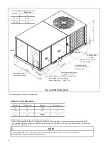
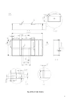
Be sure to note supply and return openings. Refer to Fig. 3 and 4 for 
information concerning rear and bottom supply and return air duct 
openings. 

Consult local codes for special requirements. 
To provide extra protection from water damage, install an additional drain pan, 
provided by installer, under the entire unit with a separate drain line. Manufac-
turer will not be responsible for any damages due to the failure to follow these 
requirements. 

4.1 INSTALL DRAIN PIPE 

Duckwork should be made and sized by installer and in accordance with Air 
Manual from Conditioning Contractors of America and local codes. 

Summary of Contents for IPRC2414KC-3

Page 1: ...MAN I IPRC14 3 0618 intensity mx INSTALLATION INSTRUCTIONS IPRC2414KC 3 IPRC3614KC 3 IPRC4814KC 3 IPRC6014KC 3 PACKAGE HEAT PUMP 14 SEER 2 5 TR 220V 1P 60Hz...

Page 2: ...REFRIGERANT CHARGE FOR H P SYSTEM 19 TABLE 7 7 REFRIGERANT CHARGE FOR H P SYSTEM 20 TABLE 7 8 REFRIGERANT CHARGE FOR H P SYSTEM 20 TABLE 7 9 REFRIGERANT CHARGE FOR H P SYSTEM 21 TABLE 7 10 REFRIGERANT...

Page 3: ...e use of unauthorized components accessories or devices may adversely affect the operation of the heat pump and may also endanger life and property The manufacturer disclaimer any responsibility for s...

Page 4: ...y transportation damage 1 1 INSPECTION Refer to Fig 2 2 2 3 for unit physical data and to Table 7 1 for electrical data If components are to be added to a unit they must meet local codes they are to b...

Page 5: ...AUTION Before lifting make sure the unit weight is distributed equally on the rigging cables so it will lift evenly Units may be moved or lifted with a forklift Slotted openings in the base rails are...

Page 6: ...irection Distance in Top Front Rear Right Left Bottom 30 60 18 12 24 0 Duct clearance 1 inch clearance for all sides of air supply duct 1 Units must be installed outdoors Over hanging structure or shr...

Page 7: ...supply air opening Bottom supply air opening Do not drill or install screw in this area Side return air opeing Bottom return air opening Bottom power entry 7 8 and 1 31 32 dia knockout Bottom control...

Page 8: ...See Fig 2 4 ROOF CURB DIMENSION The above figures for reference purpose only Supply and return air including duct support rails shown are typical for bottom duct applications For location of horizont...

Page 9: ...Fig 2 5 Roof Curb Details 9...

Page 10: ...if second connection is not used 4 Use a sealing compound on male pipe threads Install the condensate drain line NPT to spill into an open drain A closed return duct system shall be used This shall no...

Page 11: ...be kept clean When filter become dirt laden insufficient air will be delivered by the blower decreasing your units efficiency and increasing operation costs and wear and tear on the unit and controls...

Page 12: ...it breakers installed within the unit do not provide over current protection of the supply wiring and therefore may be sized larger than the branch circuit protection Supply circuit power wiring must...

Page 13: ...connect Field supplied disconnect Single phase power supply Fig 6 2 Typical Field Power Wiring Diagram R G Y W C R G Y W1 W2 C 24 volt transformer THERMOSTAT UNIT CONTROL BOARD THERMINAL STRIP B wire...

Page 14: ...18 1 20 8 41 9 45 3 5 6 7 5 27 1 31 3 53 2 58 4 7 5 10 36 1 41 7 64 4 71 4 None 24 5 None None 32 6 None 3 8 5 18 1 20 8 47 1 50 5 5 6 7 5 27 1 31 3 58 3 63 6 7 5 10 36 1 41 7 69 6 76 6 11 3 15 54 2 6...

Page 15: ...15 Table 6 2 14 SEER Physical Data The above Table data for reference only...

Page 16: ...4 992 Watts 615 602 587 575 558 542 522 498 Amps 2 84 2 8 2 76 2 72 2 67 2 63 2 58 2 51 CFM L S 2019 954 1954 923 1892 893 1819 859 1745 825 1656 782 1565 739 1459 689 RPM 891 910 931 949 968 986 1002...

Page 17: ...805 1658 783 1604 758 1549 731 1489 703 1416 669 1321 624 1179 557 RPM 781 815 849 880 908 938 969 1006 Watts 558 547 536 524 511 493 474 445 Amps 2 45 2 41 2 36 2 32 2 26 2 21 2 14 2 04 CFM L S 1658...

Page 18: ...285 305 324 345 366 392 417 440 463 113 221 244 256 269 281 301 320 341 362 388 414 437 459 109 216 240 252 265 277 297 316 337 358 385 411 433 455 105 211 236 248 261 273 293 312 333 354 381 408 429...

Page 19: ...10 434 457 109 208 237 252 267 282 298 314 338 361 384 407 430 453 105 203 233 248 263 278 294 310 334 358 381 404 427 449 36K Cooling Mode 60 62 64 66 68 70 72 74 76 78 80 82 135 336 347 358 369 380...

Page 20: ...33 457 113 209 226 243 260 278 292 306 334 362 382 402 426 450 109 203 220 237 254 272 285 298 328 357 376 395 419 443 105 197 214 231 248 266 278 293 321 347 370 388 412 436 48K Cooling Mode 60 62 64...

Page 21: ...289 309 329 348 367 393 419 446 473 109 197 206 238 260 286 306 326 345 364 390 416 444 471 105 191 204 235 257 283 303 323 342 361 387 413 441 468 60K Cooling Mode 60 62 64 66 68 70 72 74 76 78 80 82...

Page 22: ...ompressor will be off When discharge temp is 194 F the compressor will start running High pressure protection When high pressure is 638PSIG the compressor and the outdoor fan motor will stop running W...

Page 23: ...Blower fan delay 90 sec OFF Compressor and outdoor fan instant OFF Heater 1 instant OFF 4 way valve instant ON Blower instant ON Compressor and outdoor fan instant ON Heater 1 instant ON Heater 2 inst...

Page 24: ...nd indoor blower should run 4 Turn fan switch to AUTO system switch to COOL and thermostat tem perature setting below room temperature Unit should run in COOLING mode Heating Startup After normal cool...

Page 25: ...25 HP System Wiring Diagram 1 2 3 4 6 5 1 2 0 3...

Reviews: