


P. 27
Since this controller does not have any commands, there is no need to write any programs. In order to make the actuator
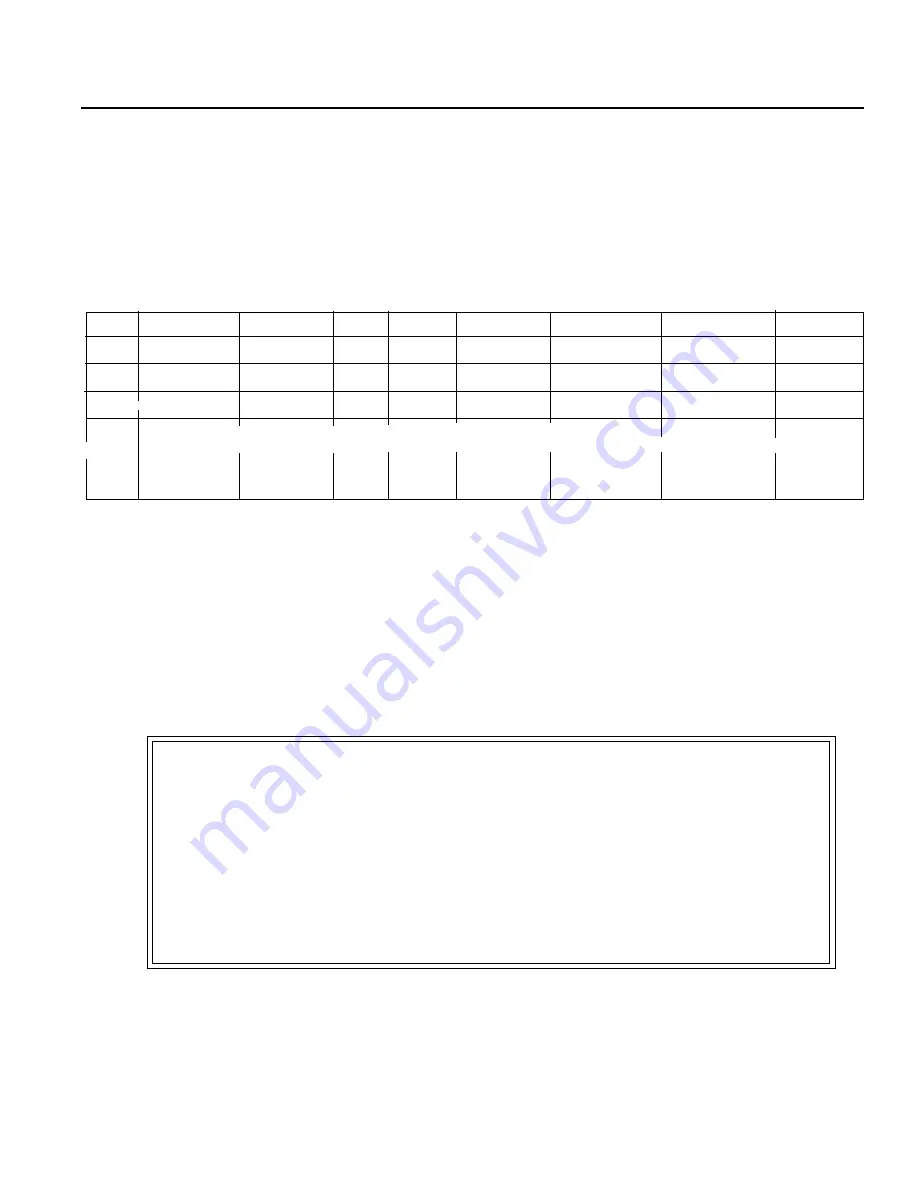
move to the assigned position, all you need to do is input the position data into the position data table. In the position table,
there are 8 columns: Position, Speed, Acc (G), Push (%), Pos. Band, MAX ACC Flag (0/1), ABS/INC Flag (0/1) and
Comments. The position table below is displayed by the Teaching Pendant. In the position data, there is Absolute which
inputs distance from home, and Incremental which inputs relative transfer load from the current position.
3. Data Input (Basic)
Position Table
No.
0
1
2
.
.
15
Position (mm)
Speed (mm/s)
100
100
100
.
.
100
Pos. Band (mm)
0.1
0.1
0.1
.
.
0.1
Max ACC Flag (0/1)
0
0
0
.
.
0
Please make modifications as needed. When modifying the initial value, changes can be made on the “initial value”
of the parameter. The initial value differs depending on the actuator type. When changing the initial value.
please use “~initial value” of the parameter. The initial value will vary according to actuator type.
* “=” indicates that this is an Incremental Move (This is diplayed by the Teaching Pendant. With a PC, incremental
assigned column will display).
0
30
10
.
.
100
Caution:
For data input, please first execute from position. Input from other data will be rejected.
As for position, input may be done up to grider 2 fraction. However, data of position
is only recognizes as a multiplier of minimum resolution. In addition, the minimum resolution
will vary according to the lead of the actuator. Therefore, the grider 2 fraction of position
data that was inputted will write over according to actuator lead.
Example: Inputted value Recorded value
50.01 50.03
=*
~
~
ABS/INC Flag (0/1)
Acc (G)
0.3
0.3
0.3
.
.
0.3
Push (%)
0
0
0
.
.
0
~
~
~
~
Comments