


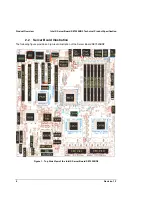


Product Overview
Intel® Server Board SE7520BD2 Technical Product Specification
10
Revision
1.3
•
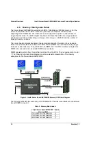
Memory mirroring allows for two copies of all data in the memory subsystem (one on
each channel) to be maintained
•
DIMM sparing allows for one DIMM per channel to be held in reserve and brought on-
line if another DIMM in the channel becomes defective. DIMM sparing and memory
mirroring are mutually exclusive of one another.
•
Hardware periodic memory scrubbing, including demand scrub support
•
Retry on uncorrectable memory errors
•
Intel® Single Device Data Correction (SDDC) x4 for memory error detection and
correction of any number of bit failures in a single x4 memory device
2.6.4 PCI
Express
(PCIe)
The Intel® E7520 MCH is the first Intel® chipset to support the new PCI Express* high-speed
serial I/O interface for superior I/O bandwidth. The scalable PCI Express interface complies with
the
PCI Express* Interface Specification, Rev 1.0a
. The MCH provide three x8 PCI Express
interfaces, each with a maximum theoretical bandwidth of 4 GB/s.
The Intel® E7520 MCH is a root class component as defined in the
PCI Express Interface
Specification, Rev 1.0a
. The PCI Express interfaces of the MCH support connection to a variety
of bridges and devices compliant with the same revision of the
PCI Express Interface
Specification, Rev 1.0a
. Refer to the
Intel® Server Board SE7520BD2 Tested Hardware and OS
List
for add-in cards tested on this platform.
2.6.5 Hub
Interface
The MCH interfaces with the Intel® 82801ER I/O Controller Hub 5-R (ICH5-R) via a dedicated
Hub Interface supporting a peak bandwidth of 266MB/s using a x4 base clock of 66 MHz.
2.7 Processor Subsystem Detail
The Server Board SE7520BD2 is designed to support one or two Intel
®
Xeon™ processors with
frequencies starting at 2.8 GHz. These newer generation processors use 90-nanometer
technology and an 800-MHz front side bus. (
Note
: Previous generations of the Xeon processor
are not supported for use on the Server Board SE7520BD2.) When two processors are
installed, both must be of identical revision, core voltage, cache size, and bus/core speed.
When only one processor is installed, it should be in the socket labeled “CPU1” and the other
socket must be empty. The support circuitry on the server board consists of the following:
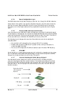
•
Dual 604-pin zero insertion force (ZIF) processor sockets
•
Processor host bus AGTL+ support circuitry
•
Reset configuration logic
•
Processor module presence detection logic
•
BSEL detection capabilities
•
CPU signal level translation
•
CEK CPU retention support.