background image

Intel Server Board SE7501BR2 Installation and Integration Guide 

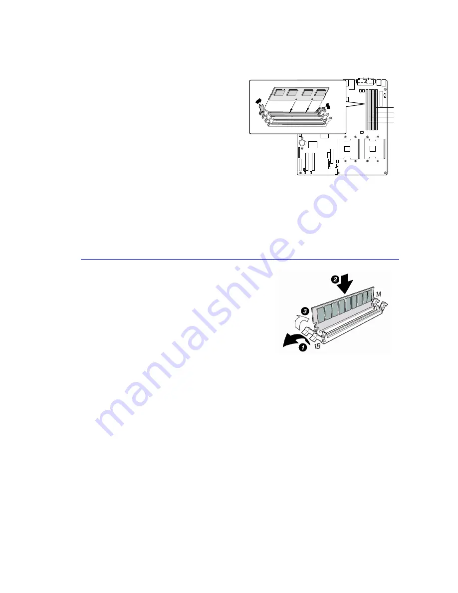
Installing Memory 

The server board supports only DDR266-
compliant DIMMs. The minimum supported 
memory configuration is 256 MB, using two 128-
MB DIMMs. The maximum configurable memory 
size is 8 GB using four 2-GB DIMMs. 

OM14665

DIMM 1A
DIMM 1B
DIMM 2A
DIMM 2B

Memory must be installed in pairs and must be 
populated per bank starting with DIMM 1A and 
1B (contiguous sockets). Although the 
SE7501BR2 server board architecture allows the 
user to mix various sizes of DIMMs between 
banks, DIMMs must be identical within each 
bank. 


NOTE


Use memory that has been tested for compatibility with the server board. For a list 
of tested memory, see: 

http://support.intel.com/support/motherboards/server/se7501br2/tested_mem.htm


If the server board is not already installed in the c
remove the server board from its packaging and place it 
on a clean ESD-protected work surface. 

hassis, 

1.


Open both DIMM socket levers.


2.


Insert DIMM, making sure the connector edge of the 
DIMM aligns correctly with the slot. 


3.


Check that the socket levers are securely latched. 
DIMMs must be populated in identical pairs.


11


Summary of Contents for SE7501BR2 - Server Board Motherboard

Page 1: ...Server Installation and Integration Guide Using the Boxed Intel Xeon Processor and Boxed Intel SE7501BR2 Server Board...

Page 2: ...COMPLETE FREE FROM DEFECTS OR SAFE FOR ITS INTENDED PURPOSE AND HEREBY DISCLAIM ALL LIABILITIES THEREFOR ANY PERSON MAKING USING OR SELLING SUCH PRODUCT OR TECHNOLOGY DOES SO AT HIS OR HER OWN RISK L...

Page 3: ...he I O Shield 9 Attaching the Label to the I O Shield 9 Installing the I O Shield 9 Installing Chassis Standoffs 10 Installing the Rubber Bumper 10 Installing the Server Board 10 Installing Memory 11...

Page 4: ...erial B Cable 20 Cable Routing Intel SC5200 Chassis Base version 20 IDE or SCSI Cables 20 Floppy and Front Panel Cables 20 Cable Routing Intel SC5200 Server Chassis Hot Swap Redundant Power Version 21...

Page 5: ...r on servers System integrators deploying servers based on boxed Intel SE7501BR2 Server Boards Our intent is to better enable system integrators particularly first time server builders to meet the com...

Page 6: ...s emf welcome asp id 37 3 Channel Customers can contact Intel customer support toll free at 1 866 655 6565 Non channel customers should use one of the numbers listed at http www intel com support 9089...

Page 7: ...sit Intel Support at http support intel com support motherboards server se7501br2 Prepare for Assembly 1 Gather tools needed Needle nose pliers Flat blade screwdriver Philips screwdriver Antistatic wr...

Page 8: ...able parts in the power supply If the power supply is malfunctioning return it to the manufacturer for servicing Electrostatic Discharge ESD CAUTION Perform the procedures in this product guide only a...

Page 9: ...he back of the chassis The shield has cutouts that match the external I O connectors such as keyboard and mouse Attaching the Gasket to the I O Shield 1 Remove the two backing strips from the gasket 2...

Page 10: ...ons marked P regardless of whether one or two processo will be installed Standoffs are included with this chassis ndoffs rs Installing the Rubber Bumper e doff he Installing the Server Board 2 ttach t...

Page 11: ...rchitecture allows the user to mix various sizes of DIMMs between banks DIMMs must be identical within each bank NOTE Use memory that has been tested for compatibility with the server board For a list...

Page 12: ...r system Do not install a terminator in the SE7501BR2 Server Board If installing a SECOND processor verify that the processors are identical in voltage and speed Do not mix processors of different typ...

Page 13: ...ip e 1 Position Make sure 2 Slide the own Note 3 Press do engage 4 Snap NOTE Install both retention clips simultaneously for the easiest installation styles may differ Verify that the t engages the sl...

Page 14: ...alignment triangle mark on the le 3 lling the Boxed Intel Xeon Processor Int S Version Choosing the Processor Socket Power version of the Intel SC5200 Server Cha If only ONE processor is to be used i...

Page 15: ...ab on the inside of the retention clip engages the slot on the heat sink during installation The center slot in the clip provides room for side to side motion while you engage the retention clip slots...

Page 16: ...wind tunnel toward the rear of the chassis as shown Attaching the Heat Sink Fan Install the processor wind tunnel center section over the heat sink The plastic tabs on the wind tunnel center section m...

Page 17: ...retention mechanism 3b 4 Then attach the fan power cable to the corresponding s board CPU fan connector erver 5 Correct assembly should look like this When installing only one processor there is no ne...

Page 18: ...nections 3 and 4 on the server board Intel SC5200 Server Chassis Hot Swap Redundant Power Version Be sure to attach each system fan to its correspondingly numbered connector on the server board System...

Page 19: ...onding component is installed A System Fan 6 upper connection G Secondary IDE B System Fan 5 lower connection H Low Voltage Differential LVD SCSI C Intelligent Platform Management Bus IPMB I HDD LED D...

Page 20: ...taching the two hex screws as shown 3 Attach the other end of the cable to the Serial B connector on the server board See Making Optional Connections to the Server Board on page 19 Cable Routing Intel...

Page 21: ...on 1 An air duct covers the processor Place the tabs on that air duct into the hinge slots on the plastic fan carrier and lower the duct into the chassis 2 Another air duct covers the PCI slot area of...

Page 22: ...ront foot are marked F and 1 2 On the back foot the middle hole should face toward the back of the chassis Location holes for the rear foot are marked F Installing into a Rack Rack Mode Installing int...

Page 23: ...er before finishing up See Installing the Access Cover on page 21 An electrical shock hazard exists if the chassis access cover is not replaced before connecting the chassis AC power 1 Connect the key...

Page 24: ...el Server Board SE7501BR2 support Web site is http support intel com support motherboards server SE7501BR2 You ll find the System Update Package at the Software and Servers link The System Update Pack...

Page 25: ...tion and the corresponding steps required to quickly get the server back up and running To get started with Intel Server Management first install the Service Partition then the operating system and fi...

Page 26: ...ool in the menu on the left side of the screen 3 In the green Make a Selection drop down menu select SMaRT Tool Install Guide Print the Guide and keep it on hand for reference 4 Review the Intel SMaRT...

Reviews: