background image

Intel® Server Board S2600CO Family TPS 


Appendix C: Integrated BMC Sensor Tables 

Revision 1.4 


Intel order number G42278-004 

123 

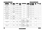
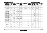
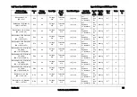
Full Sensor Name 

(Sensor name in SDR) 


Sensor 

Platform 

Applicability 

Sensor Type 

Event/ 

Reading 

Type 

Event Offset Triggers 

Contrib. To 

System Status 

Assert/

De-

assert 

Readable 

 Value/ 

Offsets 

Event 

Data 

Rearm 

Stand-

by 

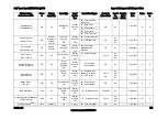
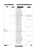
IPMI Watchdog 

(IPMI Watchdog) 

03h All 

Watchdog 2

23h 

Sensor 

Specific 

6Fh 

00 - Timer expired, 
status only 

OK As 

– 

Trig Offset


A X 

01 - Hard reset 
02 - Power down 
03 - Power cycle 
08 - Timer interrupt 

Physical Security 

(Physical Scrty) 

04h 

Chassis 

Intrusion is 

chassis-

specific 

Physical 

Security 

05h 

Sensor 

Specific 

6Fh 

00 - Chassis intrusion 

OK 

As 

and 

De 

– Trig 

Offset

A  X 

04 - LAN leash lost  

FP Interrupt 

(FP NMI Diag Int) 

05h 

Chassis -

specific 

Critical 

Interrupt 

13h 

Sensor 

Specific 

6Fh 

00 - Front panel 
NMI/diagnostic 
interrupt 

OK As 

– 

Trig 

Offset

– 

SMI Timeout 

(SMI Timeout) 

06h All 

SMI Timeout

F3h 

Digital 

Discrete 

03h 

01 – State asserted  

Fatal 

As 

and 

De 

– Trig 

Offset

A  – 

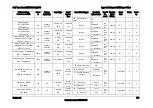
System Event Log 

(System Event Log) 

07h 

All 

Event 

Logging 

Disabled 

10h 

Sensor 

Specific 

6Fh 

02 - Log area 

reset/cleared 

OK As 

– 

Trig 

Offset

System Event 

(System Event) 

08h All 

System 

Event 

12h 


Sensor 

Specific 

6Fh 


02 - Undetermined 
system H/W failure 
04 – PEF action 


Fatal  

OK 

As 

and 

De  

As 

- Trig 

Offset

A  X 

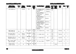
Button Sensor 

(Button)


09h All 

Button/Switch

14h 

Sensor 

Specific 

6Fh 

00 – Power Button 
02 – Reset Button 

OK AS 

Trig 

Offset

BMC Watchdog 

0Ah 

All 

Mgmt System 

Health 

28h 

Digital 

Discrete 

03h 

01 – State Asserted 

Degraded 

As 

– 

Trig Offset

Voltage Regulator Watchdog 

(

VR Watchdog

0Bh All 

Voltage 

02h 

Digital 

Discrete 

03h 

01 – State Asserted 

Fatal 

As 

and 

De 

– Trig 

Offset

M  X 

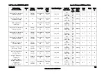
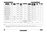
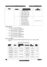
Fan Redundancy

Note1

0Ch 

Chassis-

Fan 

Generic 

00 - Fully redundant 

OK 

As 

– Trig 

Offset

A  – 

Summary of Contents for S2600CO series

Page 1: ...Intel Server Board S2600CO Family Technical Product Specification Intel order number G42278 004 Revision 1 4 September 2013 Enterprise Platforms and Services Division Marketing ...

Page 2: ...s of any features or instructions marked reserved or undefined Intel reserves these for future definition and shall have no responsibility whatsoever for conflicts or incompatibilities arising from future changes to them The products described in this document may contain design defects or errors known as errata which may cause the product to deviate from published specifications Current character...

Page 3: ...pset Functional Overview 34 3 3 1 Non Transparent Bridge 35 3 3 2 Low Pin Count LPC Interface 35 3 3 3 Universal Serial Bus USB Controller 35 3 3 4 On board Serial Attached SCSI SAS Serial ATA SATA RAID Support and Options 36 3 3 5 Manageability 38 3 4 Integrated Baseboard Management Controller Overview 39 3 4 1 Super I O Controller 40 3 4 2 Graphics Controller and Video Support 40 3 4 3 Baseboard...

Page 4: ...User Model 62 6 10 2 IPMB Communication Interface 62 6 10 3 LAN interface 62 6 10 4 Address Resoluton Protocol ARP 68 6 10 5 Internet Control Message Protocol ICMP 69 6 10 6 Virtual Local Area Network VLAN 69 6 10 7 Secure Shell SSH 70 6 10 8 Serial over LAN SOL 2 0 70 6 10 9 Platform Event Filter 70 6 10 10 LAN Alterting 71 6 10 11 Altert Policy Table 71 6 10 12 SM CLP SM CLP Lite 71 6 10 13 Embe...

Page 5: ... HSBP_I2 C Header 89 8 3 6 HDD LED Header 89 8 3 7 Internal Type A USB Connector 89 8 3 8 Internal 2mm Low Profile eUSB SSD Connector 89 8 4 Management and Security Connectors 90 8 4 1 RMM4_Lite Connector 90 8 4 2 RMM4_NIC connector 90 8 4 3 TPM Connector 90 8 4 4 PMBus Connector 91 8 4 5 Chassis Intrustion Header 91 8 4 6 IPMB Connector 91 8 5 Fan Connectors 91 8 5 1 System FAN Connectors 92 8 5 ...

Page 6: ...2 1 Power Supply DC Output Specification 107 12 1 1 Output Power Currents 107 12 1 2 Cross Loading 107 12 1 3 Standby Output 108 Appendix A Integration and Usage Tips 113 Appendix B Compatible Intel Server Chassis 114 Appendix C Integrated BMC Sensor Tables 120 Appendix D Intel Server Board S2600CO Family Specific Sensors 133 Product ID 133 ACPI S3 Sleep State Support 133 Processor Support for Int...

Page 7: ...upported Features and Functions 34 Figure 16 Intel RAID C600 Upgrade Key Connector 36 Figure 17 Integrated BMC Functional Block Diagram 39 Figure 18 Integrated BMC Hardware 39 Figure 19 Setup Utility TPM Configuration Screen 49 Figure 20 High level Fan Speed Control Process 60 Figure 21 Other Connectors and Headers 93 Figure 22 Server Board Jumper Block Locations J1E2 J1E3 J1E4 J1E6 J2J2 95 Figure...

Page 8: ...Data 76 Table 20 Additional Diagnostics on Error 76 Table 21 Intel RMM4 options kits 78 Table 22 Enabling Advanced Management Features 78 Table 23 Main Power Connector Pin out MAIN PWR 82 Table 24 CPU Power Connector Pin out CPU_1 PWR and CPU_2 PWR 82 Table 25 PCIe Card Power Connector Pin out OPT_12V_PWR 83 Table 26 SSI Front Panel Header Pin out SSI Front Panel 83 Table 27 Power Sleep LED Functi...

Page 9: ...94b Connector pin out 94 Table 55 Server Board Jumpers J1E2 J1E3 J1E4 J1E6 J1J2 95 Table 56 System Status LED 103 Table 57 POST Code Diagnostic LEDs 104 Table 58 Server Board Design Specifications 105 Table 59 MTBF Estimate 106 Table 60 Over Voltage Protection Limits 107 Table 61 Loading Conditions 107 Table 62 Voltage Regulation Limits 108 Table 63 Transient Load Requirements 108 Table 64 Capacit...

Page 10: ...List of Tables Intel Server Board S2600CO Family TPS Revision 1 4 Intel order number G42278 004 x Table 81 Integrated BMC Beep Codes 151 ...

Page 11: ...Intel Server Board S2600CO Family TPS List of Tables Revision 1 4 Intel order number G42278 004 xi This page is intentionally left blank ...

Page 12: ......
Page 13: ...e documents 1 1 Chapter Outline This document is divided into the following chapters Chapter 1 Introduction Chapter 2 Product Overview Chapter 3 Functional Architecture Overview Chapter 4 Technology Support Chapter 5 System Security Chapter 6 Platform Management Functional Overview Chapter 7 Advanced Management Features Support RMM4 Chapter 8 On board Connector Header Overview Chapter 9 Reset and ...

Page 14: ...n Intel server building blocks are used together the fully integrated system will meet the intended thermal requirements of these components It is the responsibility of the system integrator who chooses not to use Intel developed server building blocks to consult vendor datasheets and operating parameters to determine the amount of airflow required for their specific application and environmental ...

Page 15: ...uration limits Memory 16 DIMM slots 2 DIMM slots channel 4 memory channels per processor Channels A B C D E F G and H Support for Registered DDR3 Memory RDIMM LV RDIMM Unbuffered DDR3 memory UDIMM with ECC and Load Reduced DDR3 memory LR DIMM Memory DDR3 data transfer rate of 800 1066 1333 1600 and1866 MT s DDR3 standard I O voltage of 1 5V and DDR3 Low Voltage of 1 35V Chipset Intel C600 A chipse...

Page 16: ...rd Storage One low profile eUSB 2x5 pin connector to support 2mm low profile eUSB solid state devices Two AHCI SATA connectors capable of supporting up to 6Gb sec AHCI SATA 0 supports high profile vertical SATA DOM with onboard power Eight SCU SAS SATA connectors capable of supporting up to 3Gb sec Intel SAS ROC module support Optional PCIe slot form factor Intel RAID C600 Upgrade Key support prov...

Page 17: ...dentifying key feature and component locations Each connector and major component is identified by a number or letter and the description is given below the figure Callout Description Callout Description A Chassis Intrusion AH System Fan 1 Connector B Slot1 PCI Express Gen2 AI LCP C RMM4 Lite AJ Optional 12V Power Connector D Slot 2 PCI Express Gen3 AK BIOS Default E Slot 3 PCI Express Gen3 blue s...

Page 18: ...ctor P VGA AW SAS SATA_3 Connector Q CPU 2 Power connector AX SAS SATA_2 Connector R System Fan 7 AY SAS SATA_1 Connector S Serial Port A AZ SAS SATA_0 Connector T CPU 2 Fan Connector BA SAS SGPIO 0 U DIMM H1 H2 G1 G2 BB SAS SGPIO 1 V DIMM A1 A2 B1 B2 BC IPMB W CPU 1 Power connector BD HSBP_I 2 C X CPU 1 Fan Connector BE USB 5 6 front panel USB connector Y DIMM C1 C2 D1 D2 BF ME Force Update Z USB...

Page 19: ...Intel Server Board S2600CO Family TPS Product Overview Revision 1 4 7 Intel order number G42278 004 Figure 2 Intel Light Guided Diagnostic LED Identification See Chapter 10 for additional details ...

Page 20: ...Product Overview Intel Server Board S2600CO Family TPS 8 Revision 1 4 Intel order number G42278 004 Figure 3 Jumper Block Identification See Chapter 9 for additional details ...

Page 21: ... 4 9 Intel order number G42278 004 Callout Description Callout Description A Serial Port A E NIC Port 3 and 4 B Video F Diagnostics LED s C NIC Port 1 USB Port 0 top and 1 bottom G ID LED D NIC Port 2 USB Port 2 top and 3 bottom H Status LED Figure 4 Rear I O Layout ...

Page 22: ...Product Overview Intel Server Board S2600CO Family TPS 10 Revision 1 4 Intel order number G42278 004 2 2 Server Board Dimensional Mechanical Drawings Figure 5 Mounting Hole Locations 1 of 2 ...

Page 23: ...Intel Server Board S2600CO Family TPS Product Overview Revision 1 4 11 Intel order number G42278 004 Figure 6 Mounting Hole Locations 2 of 2 ...

Page 24: ...Product Overview Intel Server Board S2600CO Family TPS 12 Revision 1 4 Intel order number G42278 004 Figure 7 Major Connector Pin 1 Locations ...

Page 25: ...Intel Server Board S2600CO Family TPS Product Overview Revision 1 4 13 Intel order number G42278 004 Figure 8 Primary Side Keep out ...

Page 26: ...Product Overview Intel Server Board S2600CO Family TPS 14 Revision 1 4 Intel order number G42278 004 Figure 9 Secondary Side Keep out ...

Page 27: ...ed features and functions of the Intel processor E5 2600 or E5 2600 v2 product family the Intel C600 A chipset the Intel Ethernet Controller I350 Quad Port 1GbE chip and the Server Engines Pilot III Server Management Controller The following diagram provides an overview of the server board architecture showing the features and interconnects of each of the major sub system components Figure 10 Inte...

Page 28: ...e Previous generation Intel Xeon processors are not supported on the Intel server boards described in this document Visit the Intel website for a complete updated list of supported processors 3 1 1 Processor Socket Assembly Each processor socket of the server board is pre assembled with an Independent Latching Mechanism ILM and Back Plate which allow for secure placement of the processor and proce...

Page 29: ...oration 3 1 3 Processor Initializion Error Summary The following table describes mixed processor conditions and recommended actions for all Intel server boards and Intel server systems designed around the Intel Xeon processor E5 2600 or E5 2600 v2 product family and Intel C600 chipset product family architecture The errors fall into one of the following categories Fatal If the system can boot it p...

Page 30: ...edied Processor cores threads not identical Fatal The BIOS detects the error condition and responds as follows Logs the POST Error Code into the SEL Alerts the BMC to set the System Status LED to steady Amber Displays 0191 Processor core thread count mismatch detected message in the Error Manager Takes Fatal Error action see above and will not boot until the fault condition is remedied Processor c...

Page 31: ...p Processor microcode update failed Major The BIOS detects the error condition and responds as follows Logs the POST Error Code into the SEL Displays 816x Processor 0x unable to apply microcode update message in the Error Manager or on the screen Takes Major Error action The system may continue to boot in a degraded state depending on the setting of POST Error Pause in Setup or may halt with the P...

Page 32: ...sable Bit Intel Turbo Boost Technology Intel Intelligent Power Technology Enhanced Intel SpeedStep Technology 3 2 1 Intel QuickPath Interconnect The Intel QuickPath Interconnect is a high speed packetized point to point interconnect used in the processor The narrow high speed links stitch together processors in distributed shared memory and integrated I O platform architecture It offers much highe...

Page 33: ...d DIMM for buffered memory solutions demanding higher capacity memory subsystems Independent channel mode or lockstep mode Data burst length of eight cycles for all memory organization modes Memory DDR3 data transfer rates of 800 1066 1333 1600 and 1866 MT s 64 bit wide channels plus 8 bits of ECC support for each channel DDR3 standard I O Voltage of 1 5 V and DDR3 Low Voltage of 1 35 V 1 Gb 2 Gb ...

Page 34: ...ng with dynamic Closed Loop Thermal Throttling CLTT Memory thermal monitoring support for DIMM temperature 3 2 2 1 Supported Memory Table 3 UDIMM Support Guidelines Ranks Per DIMM and Data Width Memory Capacity Per DIMM Speed MT s and Voltage Validated by Slot per Channel SPC and DIMM Per Channel DPC Intel Server Board S2600CO 2 Slots per Channel 1DPC 2DPC 1 35V 1 5V 1 35V 1 5V E5 2600 Processor S...

Page 35: ... 1333 1600 DRx8 2GB 4GB 8GB 1066 1333 1066 1333 1600 1866 1066 1333 1066 1333 1600 SRx4 2GB 4GB 8GB 1066 1333 1066 1333 1600 1866 1066 1333 1066 1333 1600 DRx4 4GB 8GB 16GB 1066 1333 1066 1333 1600 1866 1066 1333 1066 1333 1600 QRx4 8GB 16GB 32GB 800 1066 800 800 QRx8 4GB 8GB 16GB 800 1066 800 800 Table 5 LRDIMM Support Guidelines Ranks Per DIMM and Data Width Memory Capacity Per DIMM Speed MT s a...

Page 36: ...r may be installed without populating the associated memory slots provided a second processor is installed with associated memory In this case the memory is shared by the processors However the platform suffers performance degradation and latency due to the remote memory Processor sockets are self contained and autonomous However all memory subsystem support such as Memory RAS Error Management in ...

Page 37: ...not allowed per platform Mixing of DDR3 voltages is not validated within a socket or across sockets by Intel If 1 35V DDR3L and 1 50V DDR3 DIMMs are mixed the DIMMs will run at 1 50V Mixing of DDR3 operating frequencies is not validated within a socket or across sockets by Intel If DIMMs with different frequencies are mixed all DIMMs will run at the common lowest frequency Quad rank RDIMMs are sup...

Page 38: ...em in the main page of the BIOS setup This total is the same as the amount described by the first bullet above If Display Logo is disabled the BIOS display the total system memory on the diagnostic screen at the end of POST This total is the same as the amount described by the first bullet above Note Some server operating systems do not display the total physical memory installed What is displayed...

Page 39: ...aximum read bandwidth for a given rank is half of peak There is another drawback in using lockstep mode that is higher power consumption since the total activation power is about twice of the independent channel operation if comparing to same type of DIMMs 3 2 2 4 3 Mirror Mode Memory mirroring mode is the mechanism by which a component of memory is mirrored In mirrored mode when a write is perfor...

Page 40: ...ltiple bit errors when data is read and to correct single bit errors 3 2 2 5 2 1 Correctable Memory ECC Error Handling A Correctable ECC Error is one in which a single bit error in memory contents is detected and corrected by use of the ECC Hamming Code included in the memory data For a correctable error data integrity is preserved but it may be a warning sign of a true failure to come Note that s...

Page 41: ... failing ranks of DIMMs Rank Sparing is strictly channel and rank oriented Each memory channel is a Sparing Domain For Rank Sparing to be available as a RAS option there must be 2 or more single rank or dual rank DIMMs or at least one quad rank DIMM installed on each memory channel Rank Sparing Mode is enabled disabled in the Memory RAS and Performance Configuration screen in the F2 BIOS Setup Uti...

Page 42: ...rank and the first event is logged What Mirroring primarily protects against is the possibility of an Uncorrectable ECC Error occurring with critical data in process Without Mirroring the system would be expected to Blue Screen and halt possibly with serious impact to operation But with Mirroring Mode in operation an Uncorrectable ECC Error from one channel becomes a Mirroring Fail Over MFO event ...

Page 43: ...local host memory domain from the remote host memory domain while enabling status and data exchange between the two domains Intel QuickData Technology Used for efficient high bandwidth data movement between two locations in memory or from memory to I O Dual Gb Dual Gb Dual Gb Dual Gb DMI2 PCIe Gen2 x4 4GB s PCIe Gen3 x16 32GB s PCIe Gen3 x4 8GB s PCIe Gen3 x4 8GB s PCIe Gen2 x4 4GB s Figure 14 Fun...

Page 44: ...cessor configurations 3 2 3 2 Intel Integrated RAID Option The server board provides support for Intel Integrated RAID modules with PCIe form factor These optional modules attach to PCIe slots on the server board and are supported by x8 PCIe Gen3 signals from the IIO module of the CPU processor Features of this option include SKU options to support full or entry level hardware RAID Dual core 6Gb S...

Page 45: ...hanical 3 2 3 4 Network Interface Network connectivity is provided by means of an onboard Intel Ethernet Controller 1350 AM4 providing up to four 10 100 1000 Mb Ethernet ports The NIC chip is supported by implementing x4 PCIe Gen3 signals from the IIO module of the CPU 1 processor On the Intel Server Board S2600CO four external 10 100 1000 Mb RJ45 Ethernet ports are provided Each Ethernet port dri...

Page 46: ... overview of the key features and functions of the Intel C600 A chipset used on the server board For more comprehensive chipset specific information refer to the Intel C600 Series chipset documents listed in the Reference Documents list SCU 7 4 SCU 3 0 P 5 2 P 1 0 LHS RHS USB 7 6 5 1 USB 13 11 PCIe Gen2 x4 4GB s Figure 15 Functional Block Diagram Chipset Supported Features and Functions On the Int...

Page 47: ... port is connected to the root port on the first system making this a fully symmetric configuration NTB Port to Root Port Based Connection Non Symmetric Configuration The root port on the first system is connected to the NTB port of the second system And it is not necessary for the first system to be of the Intel Xeon Processor E5 2600 or E5 2600 v2 product family 3 3 2 Low Pin Count LPC Interface...

Page 48: ...M header with onboard power Note The connectors labeled SATA SAS_4 to SATA SAT_7 is NOT functional by default and is only enabled with the addition of an Intel RAID C600 Upgrade Key option supporting 8 SATA SAS ports The server board is capable of supporting additional chipset embedded SAS SATA and RAID options from the SCU controller when configured with one of several available Intel RAID C600 U...

Page 49: ...ing the F2 BIOS Setup Utility accessed during system POST options are available to enable disable SW RAID and select which embedded software RAID option to use 3 3 4 1 Intel Embedded Server RAID Technology 2 ESRT2 Features of the embedded software RAID option Intel Embedded Server RAID Technology 2 ESRT2 include the following Based on LSI MegaRAID Software Stack Software RAID with system providing...

Page 50: ...tes several functions designed to manage the system and lower the total cost of ownership TCO of the system These system management functions are designed to report errors diagnose the system and recover from system lockups without the aid of an external microcontroller TCO Timer The chipset s integrated programmable TCO timer is used to detect system locks The first expiration of the timer genera...

Page 51: ...r Overview The server board utilizes the I O controller Graphics Controller and Baseboard Management features of the Server Engines Pilot III Server Management Controller The following is an overview of the features as implemented on the server board from each embedded controller Figure 17 Integrated BMC Functional Block Diagram Figure 18 Integrated BMC Hardware ...

Page 52: ...ce 3 4 1 2 Wake up Control The super I O contains functionality that allows various events to power on and power off the system 3 4 2 Graphics Controller and Video Support The integrated graphics controller provides support for the following features as implemented on the server board Integrated Graphics Core with 2D Hardware accelerator DDR 3 memory interface with 16MB of memory allocated and rep...

Page 53: ...the primary video device The add in video card is allocated resources and is considered the secondary video device The BIOS Setup utility provides options to configure the feature as follows Table 12 Video mode On board Video Enabled Disabled Dual Monitor Video Enabled Disabled Shaded if on board video is set to Disabled 3 4 3 Baseboard Management Controller The server board utilizes the following...

Page 54: ... CD DVD ROM and floppy USB 1 1 USB 2 0 interface for PS2 to USB bridging remote Keyboard and Mouse Hardware Based Video Compression and Redirection Logic Supports both text and Graphics redirection Hardware assisted Video redirection using the Frame Processing Engine Direct interface to the Integrated Graphics Controller registers and Frame buffer Hardware based encryption engine 3 4 3 2 Integrate...

Page 55: ...rily concerned I O hardware assist features complementary to but independent of VT d Intel VT x is designed to support multiple software environments sharing same hardware resources Each software environment may consist of OS and applications The Intel Virtualization Technology features can be enabled or disabled in the BIOS setup The default behavior is disabled Intel VT d is supported jointly by...

Page 56: ...ity to understand cooling demand from a temperature and airflow perspective Detection and correction of hot spots Control capability that reduces platform power consumption to protect a server in a hot spot Ability to monitor server inlet temperatures to enable greater rack utilization in areas with adequate cooling The requirements listed above are those that are addressed by the C600 chipset Man...

Page 57: ...tion Processor Power monitoring and limiting The ME NM monitors processor or socket power consumption and holds average power over duration It can be queried to return actual power at any given instant The monitoring process of the ME will be used to limit the processor power consumption through processor P states and dynamic core allocation Core allocation at boot time Restrict the number of core...

Page 58: ...password is entered a popup warning message will be displayed although the weak password will be accepted Once set a password can be cleared by changing it to a null string This requires the Administrator password and must be done through BIOS Setup or other explicit means of changing the passwords Clearing the Administrator password will also clear the User password Alternatively the passwords ca...

Page 59: ...up TCG A TPM device is optionally installed onto a high density 14 pin connector labeled TPM on the server board and is secured from external software attacks and physical theft A pre boot environment such as the BIOS and operating system loader uses the TPM to collect and store unique measurements from multiple factors within the boot process to create a system fingerprint This unique fingerprint...

Page 60: ...nhibits BIOS Setup entry and boots directly to the operating system which requested the TPM command s 5 2 3 TPM Security Setup Options The BIOS TPM Setup allows the operator to view the current TPM state and to carry out rudimentary TPM administrative operations Performing TPM administrative options through the BIOS setup requires TPM physical presence verification Using BIOS TPM Setup the operato...

Page 61: ... TPM settings through the security screen To access this screen from the Main screen select the Security option Main Advanced Security Server Management Boot Options Boot Manager Administrator Password Status Installed Not Installed User Password Status Installed Not Installed Set Administrator Password 1234aBcD Set User Password 1234aBcD Front Panel Lockout Enabled Disabled TPM State Enabled Acti...

Page 62: ...S setting returns to No Operation on every boot cycle by default 5 3 Intel Trusted Execution Technology The Intel Xeon Processor E5 4600 2600 2400 1600 Product Families support Intel Trusted Execution Technology Intel TXT which is a robust security environment Designed to help protect against software based attacks Intel Trusted Execution Technology integrates new security features and capabilitie...

Page 63: ...itor an OS or an application In addition Intel Trusted Execution Technology requires the system to include a TPM v1 2 as defined by the Trusted Computing Group TPM PC Client Specifications Revision 1 2 When available Intel Trusted Execution Technology can be enabled or disabled in the processor from a BIOS Setup option ...

Page 64: ...Support and utilization for some features is dependent on the server platform in which the server board is integrated and any additional system level components and options that may be installed 6 1 1 IPMI 2 0 Features Baseboard Management Controller BMC IPMI Watchdog timer Messaging support including command bridging and user session support Chassis device functionality including power reset cont...

Page 65: ...enerates diagnostic beep codes for fault conditions System GUID storage and retrieval Front panel management The BMC controls the system status LED and chassis ID LED It supports secure lockout of certain front panel functionality and monitors button presses The chassis ID LED is turned on using a front panel button or a command Power state retention Power fault analysis Intel Light Guided Diagnos...

Page 66: ...ol DCMI 1 1 compliance product specific Support for embedded web server UI in Basic Manageability feature set Enhancements to embedded web server o Human readable SEL o Additional system configurability o Additional system monitoring capability o Enhanced on line help Enhancements to KVM redirection o Support for higher resolution Support for EU Lot6 compliance Management support for PMBus rev1 2 ...

Page 67: ...SDRs Fans may be set to a fixed state or basic fan management can be applied The BMC detects that the system has exited the ACPI S1 sleep state when the BIOS SMI handler notifies it S2 No Not supported S3 No Not supported S4 No Not supported S5 Yes Soft off The front panel buttons are not locked The fans are stopped The power up process goes through the normal boot process The power reset front pa...

Page 68: ...n the uBOOT code This count is cleared upon cycling of power to the BMC or upon continuous operation of the BMC without a watchdog generated reset occurring for a period of greater than 30 minutes The BMC FW logs a SEL event indicating that a watchdog generated BMC reset either soft or hard reset has occurred This event may be logged after the actual reset has occurred Refer sensor section for det...

Page 69: ...he processor status sensor value The FRB2 failure does not affect the front panel LEDs 6 6 Sensor Monitoring The BMC monitors system hardware and reports system health Some of the sensors include those for monitoring Component board and platform temperatures Board and platform voltages System fan presence and tach Chassis intrusion Front Panel NMI Front Panel Power and System Reset Buttons SMI tim...

Page 70: ...al and a separate configurable fan control policy A fan domain can have a set of temperature and fan sensors associated with it These are used to determine the current fan domain state A fan domain has three states sleep nominal and boost The sleep and boost states have fixed but configurable through OEM SDRs fan speeds associated with them The nominal state has a variable speed determined by the ...

Page 71: ... minimum fan speed curves The valid range is from 0 to 100 which stands for 0 to 100 PWM adding to the minimum fan speed This feature is valid when Quiet Fan Idle Mode is at Enabled state The default setting is 0 6 9 1 5 Quiet Fan Idle Mode This feature can be Enabled or Disabled If enabled the fan will either stopped or shift to a lower speed when the aggregate sensor temperatures are satisfied i...

Page 72: ...4 9 CPU VR Temperature Sensors4 7 DIMM VR Temperature Sensors4 7 Integrated BMC Temperature Sensor4 7 Global Aggregate Thermal Margin Sensors3 8 Note 1 For fan speed control in Intel chassis 2 For fan speed control in third party chassis 3 Temperature margin from throttling threshold 4 Absolute temperature 5 PECI value 6 On die sensor 7 On board sensor 8 Virtual sensor 9 Available only when PSU ha...

Page 73: ...g Static CLTT CLTT control registers are configured by BIOS MRC during POST The memory throttling is run as a closed loop system with the DIMM temperature sensors as the control input Otherwise the system does not change any of the throttling control registers in the embedded memory controller during runtime Dynamic Open Loop Thermal Throttling Dynamic OLTT OLTT control registers are configured by...

Page 74: ... administrator privilege level 3 All user passwords including passwords for 1 and 2 may be modified 4 User IDs 3 15 may be used freely with the condition that user names are unique Therefore no other users can be named Null root or any other existing user name 6 10 2 IPMB Communication Interface The IPMB communication interface used the 100 KB s version of an I2 C bus as its physical medium For mo...

Page 75: ...traffic The baseboard NIC s are connected to a single BMC RMII RGMII port that is configured for RMII operation The NC SI protocol is used for this connection and provides a 100 Mb s full duplex multi drop interface which allows multiple NICs to be connected to the BMC The physical layer is based upon RMII however RMII is a point to point bus whereas NC SI allows 1 master and up to 4 slaves The lo...

Page 76: ...e NIC 4 MAC address NIC 1 MAC address 3 for OS usage BMC LAN channel 1 MAC address NIC1 MAC address 4 BMC LAN channel 2 MAC address NIC1 MAC address 5 BMC LAN channel 3 RMM MAC address NIC1 MAC address 6 The printed MAC address on the server board and or server system is assigned to NIC1 on the server board For security reasons embedded LAN channels have the following default setting IP Address St...

Page 77: ...ertisements from the local router The IP Prefix and Gateway are read only parameters to the BMC user in this mode Static Manual The IP Prefix and Gateway parameters are manually configured by the user The BMC ignores any Router Advertisement messages received over the network DHCPv6 The IP comes from running a DHCPv6 client on the BMC and receiving the IP from a DHCPv6 server somewhere on the netw...

Page 78: ...he BMC s network interfaces requires using the Set LAN Configuration Parameter command to configure LAN configuration parameter 4 IP Address Source The BMC supports this parameter as follows 1h static address manually configured Supported on all management NICs This is the BMC s default value 2h address obtained by BMC running DHCP Supported only on embedded management NICs IP Address Source value...

Page 79: ...ateway IP address before the BMC s IP address and subnet mask are set the default gateway IP address is not updated and the BMC returns 0Xcc If the BMC s IP address on a LAN channel changes while a LAN session is in progress over that channel the BMC does not take action to close the session except through a normal session timeout The remote client must re sync with the new IP address The BMC s ne...

Page 80: ... last Block request in this series In other words Byte 2 is equal to Update is complete on that request Whenever Block Size 16 the Block data bytes must end with a NULL Character or Byte 0 All Block write requests are updated into a local Memory byte array When Byte 2 is set to Upgrade is Complete the Local Memory is committed to the NV Storage Local Memory is reset to NULL after changes are commi...

Page 81: ...e the given VLAN tag ID Valid VLAN IDs are 1 through 4094 VLAN IDs of 0 and 4095 are reserved per the 802 1Q VLAN Specification Only one VLAN can be enabled at any point in time on a LAN channel If an existing VLAN is enabled it must first be disabled prior to configuring a new VLAN on the same LAN channel Parameter 12 VLAN Priority of the Set LAN Config Parameters IPMI command is now implemented ...

Page 82: ...hen the IPMI over LAN session is established 6 10 9 Platform Event Filter The BMC includes the ability to generate a selectable action such as a system power off or reset when a match occurs to one of a configurable set of events This capability is called Platform Event Filtering or PEF One of the available PEF actions is to trigger the BMC to send a LAN alert to one or more destinations The BMC s...

Page 83: ...ftware The format of the MIB file is covered under RFC 2578 6 10 11 Altert Policy Table Associated with each PEF entry is an alert policy that determines which IPMI channel the alert is to be sent There is a maximum of 20 alert policy entries There are no pre configured entries in the alert policy table because the destination types and alerts may vary by user Each entry in the alert policy table ...

Page 84: ...port that is enabled for server management capabilities 6 10 13 Embeded Web Server Integrated BMC Base manageability provides an embedded web server and an OEM customizable web GUI which exposes the manageability features of the Integrated BMC base feature set It is supported over all on board NICs that have management connectivity to the Integrated BMC as well as an optional dedicated add in mana...

Page 85: ...Intel for debug purposes Virtual Front Panel The Virtual Front Panel provides the same functionality as the local front panel The displayed LEDs match the current state of the local panel LEDs The displayed buttons for example power button can be used in the same manner as the local buttons Display of ME sensor data Only sensors that have associated SDRs loaded will be displayed Ability to save th...

Page 86: ...ID LED changes to solid on If the button is pressed again then the chassis ID LED turns off Note that the chassis ID will turn on because of the original chassis ID button press and will reflect in the Virtual Front Panel after VFP sync with BMC Virtual Front Panel will not reflect the chassis LED software blinking by the software command as there is no mechanism to get the chassis ID Led status O...

Page 87: ...pply black box data and power supply asset information Power supply vendors are adding the capability to store debug data within the power supply itself The platform debug feature provides a means to capture this data for each installed power supply The data can be analyzed by Intel for failure analysis and possibly provided to the power supply vendor as well The BMC gets this data from the power ...

Page 88: ...Filesystem List Info BMC Network Info BMC Syslog BMC Configuration Data External BMC Data Hex SEL listing Human readable SEL listing Human readable sensor listing External BIOS Data POST codes for the two most recent boots System Data SMBIOS table for the current boot 256 bytes of PCI config data for each PCI device Table 20 Additional Diagnostics on Error Category Data System Data First 256 bytes...

Page 89: ...otocol supported by the BMC for the purpose of authentication and authorization The BMC user connects with an LDAP server for login authentication This is only supported for non IPMI logins including the embedded web UI and SM CLP IPMI users passwords and sessions are not supported over LDAP LDAP can be configured IP address of LDAP server port and do on from the BMC s Embedded Web UI LDAP authent...

Page 90: ...gement Module 4 Package includes 2 modules 1 key for advance features 2 Dedicated NIC for management Dedicated NIC for management traffic Higher bandwidth connectivity for KVM and media Redirection If the optional Dedicated Server Management NIC is not used then the traffic can only go through the onboard Integrated BMC shared NIC and will share network bandwidth with the host system Advanced mana...

Page 91: ... at 60Hz 1920x1200 at 60Hz 1920x1080 1080p 1920x1200 WUXGA 1650X1080 WSXGA 7 1 1 Remote Console The Remote Console is the redirected screen keyboard and mouse of the remote host system To use the Remote Console window of your managed host system the browser must include a Java Runtime Environment plug in If the browser has no Java support such as with a small handheld device the user can maintain ...

Page 92: ...across an AC power loss 7 1 5 Usage As the server is powered up the remote KVM session displays the complete BIOS boot process The user is able interact with BIOS setup change and save settings as well as enter and interact with option ROM configuration screens At least two concurrent remote KVM sessions are supported It is possible for at least two different users to connect to same server and st...

Page 93: ...ll require the session to be re established The mounted device is visible to and useable by managed system s OS and BIOS in both pre boot and post boot states The mounted device shows up in the BIOS boot order and it is possible to change the BIOS boot order to boot from this remote device It is possible to install an operating system on a bare metal server no OS present using the remotely mounted...

Page 94: ... a 24 pin power connector The connector is labeled as MAIN PWR on the server board The following tables provide the pin out of MAIN PWR connector Table 23 Main Power Connector Pin out MAIN PWR Pin Signal name Pin Signal name 1 P3V3 13 P3V3 2 P3V3 14 N12V 3 GND 15 GND 4 P5V 16 FM_PS_EN_PSU_N 5 GND 17 GND 6 P5V 18 GND 7 GND 19 GND 8 PWRGD_PS_PWROK_PSU_R1 20 NC_PS_RES_TP 9 P5V_STBY_PSU 21 P5V 10 P12V...

Page 95: ...he server board is a 30 pin SSI compatible front panel header which provides for various front panel features including Power Sleep Button System ID Button System Reset Button NMI Button NIC Activity LEDs Hard Drive Activity LEDs System Status LED System ID LED On the server board this header is labeled SSI FRONT PANEL The following table provides the pin out for this header Table 26 SSI Front Pan...

Page 96: ...ng system are up and running 8 2 1 2 System ID Button and LED Support Pressing the System ID Button will toggle both the ID LED on the front panel and the Blue ID LED on the server board on and off The System ID LED is used to identify the system for maintenance when installed in a rack of similar server systems The System ID LED can also be toggled on and off remotely using the IPMI Chassis Ident...

Page 97: ... on the back edge of the server board viewable from the back of the system Both LEDs are tied together and will show the same state The System Status LED states are driven by the on board platform management sub system The following table provides a description of each supported LED state Table 29 System Status LED State Definitions Color State Criticality Description Off System is not operating N...

Page 98: ...g has reset the BMC Power Unit sensor offset for configuration error is asserted HDD HSC is off line or degraded Amber 1 Hz blink Non critical System is operating in a degraded state with an impending failure warning although still functioning Non fatal alarm system is likely to fail Critical threshold crossed Voltage temperature including HSBP temp input power to power supply output current for m...

Page 99: ...e following table provides the connector pin out Table 30 Front Panel USB Connector Pin out USB5 6 Pin Signal Name Pin Signal Name 1 5V 2 5V 3 USB_N 4 USB_N 5 USB_P 6 USB_P 7 GND 8 GND 10 8 2 3 Intel Local Control Panel Connector The server board includes a 7 pin connector that is used when the system is configured with Intel Local Control Panel with LCD support On the server board this connector ...

Page 100: ...up to four SATA ports capable of transfer rates of up to 3Gb s The connector labeled SATA SAS_4 to SATA SAS_7 is only enabled when an optional Intel RAID C600 Upgrade Key is installed See Table 10 for a complete list of supported storage upgrade keys The following tables provide the pin out for each connector Table 33 SATA SAS Connector Pin out SATA SAS_0 to SATA SAS_7 Pin Signal Name 1 GND 2 SATA...

Page 101: ... board this header is labeled HDD LED The header has the following pin out Table 37 Hard Drive Acitivity Header Pin out HDD_LED Pin Signal Name 1 LED_HDD_ACT_N 2 TP_LED_HDD_ACT 8 3 7 Internal Type A USB Connector The server board includes one internal Type A USB connector labeled USB_4 The following table provides the pin out for this connector Table 38 Internal Type A USB 2 0 Connector Pin out US...

Page 102: ...erver board this connector is labeled as RMM4_Lite The following table provides the pin out for this connector Table 40 RMM4_Lite Connector Pin out RMM4_Lite Pin Signal Name Pin Signal Name 1 P3V3_AUX 2 SPI_IBMC_BK_DI 4 SPI_IBMC_BK_CLK 5 SPI_IBMC_BK_DO 6 GND 7 SPI_IBMC_BK_CS_N 8 GND 8 4 2 RMM4_NIC connector Table 41 RMM4_NIC Connector Pin out RMM4_NIC Pin Signal Name Pin Signal Name 1 3V3_AUX 2 MD...

Page 103: ...when the chassis is configured with a chassis intrusion switch On the server board this header is labeled CHAS INTR The header has the following pin out Table 44 Chassis Intrusion Header Pin out CHAS INTR Pin Signal Description 1 FP_CHASSIS_INTRUSION 2 GND Table 45 Chassis Instrusion Header State Description Header state Description PINS 1 and 2 CLOSED IBMC_CHASSIS_N is pulled HIGH Chassis cover i...

Page 104: ... Description 1 GND 2 12V 3 TACH 4 PWM 5 PRSNT 6 FAULT Table 48 4 pin System FAN Connector Pin out SYS_FAN_7 Pin Signal Description 1 GND 2 12V 3 TACH 4 PWM 8 5 2 CPU FAN Connector The server board also provides support for two CPU cooling fans Each 4 pin connector is monitored and controlled by platform management On the server board each CPU fan connector is labeled as CPU_1FAN and CPU_2FAN The f...

Page 105: ...wing pin out Table 51 Serial B Connector Pin out SERIAL_B Pin Signal Name Pin Signal Name 1 SPA_DCD 2 SPA_DSR 3 SPA_SIN_N 4 SPA_RTS 5 SPA_SOUT_N 6 SPA_CTS 7 SPA_DTR 8 SPA_RI 9 GND 8 6 3 Video Connector The following table details the pin out definition of the external VGA connector Table 52 Rear VGA Video Connector Pinout VGA Pin Signal Name 1 RED 2 GREEN 3 BLUE 4 N C 5 GND 6 GND 7 GND 8 GND 9 P5V...

Page 106: ...s header is labeled FAN BOARD_I2 C The header has the following pin out Table 53 HSBP 4 PIN I2 C BUS Connector pin out FAN BOARD_I2 C Pin Signal Name 1 SMB_3V3SB_DAT 2 GND 3 SMB_3V3SB_CLK 4 P3V_SB 8 7 2 IEEE 1394b Connector Note Only Intel Server Board S2600COE includes these two IEEE 1394b connectors The server board includes two red 10 pin IEEE 1394b connectors On the server board this header is...

Page 107: ...ocations J1E2 J1E3 J1E4 J1E6 J2J2 Note 1 For safety purposes the power cord should be disconnected from a system before removing any system components or moving any of the on board jumper blocks 2 System Update and Recovery files are included in the System Update Packages SUP posted to Intel s web site Table 55 Server Board Jumpers J1E2 J1E3 J1E4 J1E6 J1J2 Jumper Name Pins System Results J1E6 BIOS...

Page 108: ...Intel server boards The following procedure outlines the new usage model 9 1 1 Set BIOS to default that is Clearing the CMOS To clear the CMOS perform the following steps 1 Power down the server Do not unplug the power cord 2 Open the server chassis For instructions see your server chassis documentation 3 Move jumper from the default operating position covering pins 1 and 2 to the reset clear posi...

Page 109: ...he default operating position covering pins 1 and 2 to the enabled position covering pins 2 and 3 4 Close the server chassis 5 Reconnect the AC cord and power up the server 6 Perform the Integrated BMC firmware update procedure as documented in the README TXT file that is included in the given Integrated BMC firmware update package After successful completion of the firmware update process the fir...

Page 110: ...server chassis 9 Move jumper from the enabled position covering pins 2 and 3 to the disabled position covering pins 1 and 2 10 Close the server chassis 11 Reconnect the AC cord and power up the server 9 4 BIOS Recovery Jumper The following procedure boots the recovery BIOS and flashes the normal BIOS 1 Turn off the system power 2 Move the BIOS recovery jumper to the recovery state 3 Insert a boota...

Page 111: ...Several server management features of these server boards require a 5V stand by voltage supplied from the power supply The features and components that require this voltage must be present when the system is powered down The LED is illuminated when AC power is applied to the platform and 5V stand by voltage is supplied to the server board by the power supply Figure 23 5 Volt Stand by Status LED Lo...

Page 112: ...Light Guided Diagnostics Intel Server Board S2600CO Family TPS Revision 1 4 Intel order number G42278 004 100 Figure 24 Fan Fault LED s Location ...

Page 113: ... as shown in the following figure The DIMM fault LED illuminates when the corresponding DIMM slot has memory installed and a memory error occurs Figure 25 DIMM Fault LED s Location 10 4 System ID LED System Status LED and POST Code Diagnostic LEDs The server boards provide LEDs for system ID system status and POST code These LEDs are located in the rear I O area of the server board as shown in the...

Page 114: ...ic LEDs 10 4 1 System ID LED You can illuminate the blue System ID LED using either of the following two mechanisms By pressing the System ID Button on the system front control panel the ID LED displays a solid blue color until the button is pressed again By issuing the appropriate hex IPMI Chassis Identify value the ID LED will either blink blue for 15 seconds and turn off or will blink indefinit...

Page 115: ...verable temperature threshold asserted o Non recoverable voltage threshold asserted o Power fault Power Control Failure o Fan redundancy lost insufficient system cooling This does not apply to non redundant systems o Power supply redundancy lost insufficient system power This does not apply to non redundant systems Note This state also occurs when AC power is first applied to the system This indic...

Page 116: ...ily TPS Revision 1 4 Intel order number G42278 004 104 Table 57 POST Code Diagnostic LEDs A Diagnostic LED 7 MSB LED E Diagnostic LED 3 B Diagnostic LED 6 F Diagnostic LED 2 C Diagnostic LED 5 G Diagnostic LED 1 D Diagnostic LED 4 H Diagnostic LED 0 LSB LED ...

Page 117: ...vironmental conditions Intel Corporation cannot be held responsible if components fail or the server board does not operate correctly when used outside any of its published operating or non operating limits Disclaimer Note Intel ensures the unpackaged server board and system meet the shock requirement mentioned above through its own chassis development and system configuration It is the responsibi...

Page 118: ... The following is the calculated Mean Time Between Failures MTBF 30 C ambient air These values are derived using a historical failure rate and multiplied by factors for application electrical and or thermal stress and for device maturity You should view MTBF estimates as reference numbers only Calculation Model Telcordia Issue 1 method I case 3 Operating Temperature Server in 30 C ambient air Oper...

Page 119: ...amily Technical Product Specification 12 1 Power Supply DC Output Specification 12 1 1 Output Power Currents The following tables define the minimum power and current ratings The power supply must meet both static and dynamic voltage regulation requirements for all conditions Table 60 Over Voltage Protection Limits Parameter Min Max Peak Unit 3 3V 0 5 18 0 A 5V 0 3 15 0 A 12V1 0 7 24 0 28 0 A 12V2...

Page 120: ...Vrms 12V2 4 5 11 52 12 00 12 60 Vrms 12V3 4 5 11 52 12 00 12 60 Vrms 12V 10 10 13 20 12 00 10 80 Vrms 5VSB 4 5 4 80 5 00 5 25 Vrms 12 1 3 2 Dynamic Loading The output voltages remain within limits specified for the step loading and capacitive loading specified in the table below The load transient repetition rate is tested between 50Hz and 5kHz at duty cycles ranging from 10 90 The load transient ...

Page 121: ...utput up to 500mV There is neither additional heat generated nor stressing of any internal components with this voltage applied to any individual or all outputs simultaneously It also does not trip the protection circuits during turn on The residual voltage at the power supply outputs for no load condition does not exceed 100mV when AC voltage is applied and the PSON signal is de asserted 12 1 3 6...

Page 122: ... to within regulation limits Tvout_rise within 2 to 50ms except for 5VSB it is allowed to rise from 1 to 25ms The 3 3V 5V and 12V1 12V2 12V3 output voltages start to rise approximately at the same time All outputs rise monotonically Each output voltage reach regulation within 50ms Tvout_on of each other during turn on the power supply Each output voltage fall out of regulation within 400ms Tvout_o...

Page 123: ...Tested at 75 of maximum load 12 ms Tpson_on_delay Delay from PSON active to output voltages within regulation limits 5 400 ms Tpson_pwok Delay from PSON deactivate to PWOK being de asserted 50 ms Tpwok_on Delay from output voltages within regulation limits to PWOK asserted at turn on 100 500 ms Tpwok_off Delay from PWOK de asserted to output voltages 3 3V 5V 12V 12V dropping out of regulation limi...

Page 124: ...umber G42278 004 112 Figure 29 Turn On Off Timing Power Supply Signals AC Input Vout PWOK 5VSB PSON Tsb_on_delay TAC_on_delay Tpwok_on Tvout_holdup Tpwok_holdup Tpson_on_delay Tsb_on_delay Tpwok_on Tpwok_off Tpwok_off Tpson_pwok Tpwok_low Tsb_vout AC turn on off cycle PSON turn on off cycle T5VSB_holdup ...

Page 125: ...and UDIMMs is not supported For the best performance the number of DDR3 DIMMs installed should be balanced across both processor sockets and memory channels For example a two DIMM configuration performs better than a one DIMM configuration In a two DIMM configuration DIMMs should be installed in DIMM sockets A1 and D1 A six DIMM configuration DIMM sockets A1 B1 C1 D1 E1 and F1 performs better than...

Page 126: ...ackable feature A 550 W Fixed Power supply B I O Ports C Alternate RMM4 Knockout D PCI Add in Board Slot Covers E AC Input Power Connector F Serial Port Knockout G A Kensington Cable Lock Mounting Hole H Padlock Loop I Alternate RMM4 Knockout J Front Control Panel K 5 25 Peripheral Bays L CPU Zone System Fan Fixed System Fan 2 M Fixed Hard Drive Carrier Tray N PCI Zone System Fan Fixed System Fan ...

Page 127: ... Board Slot Covers F Serial Port Knockout G A Kensington Cable Lock Mounting Hole H Padlock Loop I Alternate RMM4 Knockout J Hot swap System Fan 5 K Front Control Panel L Hot swap System Fan 4 M 5 25 Peripheral Bays N Hot swap System Fan 3 O Hot swap System Fan 2 P 8x3 5 Hot swap HDD Cage Q Hot swap System Fan 1 R PCI Card Retainer Figure 31 Intel Server Chassis P4000M with Hot swap Power Supply H...

Page 128: ...P4308XXMHJC two 1200 W redundant hot swap PSU five redundant hot swap 80x38mm system fans and up to eight 3 5 hot swap hard drives 6 P4208XXMHEN one 550 W non redundant fixed PSU two non redundant fixed 120x38mm system fans and up to eight 2 5 hot swap hard drives 7 P4208XXMHDR two 460 W redundant hot swap PSU two non redundant fixed 120x38mm system fans and up to eight 2 5 hot swap hard drives 8 ...

Page 129: ... P4304XXMHEN one 550 W non redundant fixed PSU two non redundant fixed 120x38mm system fans and up to four 3 5 hot swap hard drives The following table summarizes the features for all chassis combinations Table 68 Intel Server Chassis P4000M family Features Configuration P4308XXMFEN P4308XXMHEN P4308XXMFGN P4308XXMHGC P4308XXMHJC Intel Server Board Support Intel Server Board S2600CP Intel Server B...

Page 130: ...8x2 5 hot swap hard drive cage Supports up to eight 2 5 hot swap hard drives Include two 8x2 5 hot swap hard drive cage Supports up to sixteen 2 5 hot swap hard drives Expansion Slots Support up to six 6 full height full length PCI form factor cards mechanically Front Panel Power Button with LED Reset Button NMI Button ID Button with LED Four NIC LEDs Hard drive activity LED System status LED two ...

Page 131: ...0W redundant hot swap power supply with low current PDB One 460W hot swap power supply with low current PDB Two 460W redundant hot swap power supply with low current PDB One 460W hot swap power supply with low current PDB 550W non redundant fixed power supply System Cooling Two 120x38mm non redundant fans Peripherals Bays Three 3 half height 5 1 4 bays for optical devices Drive Bays Include two 8x...

Page 132: ...sholds are event generating thresholds for threshold types of sensors o u l nr c nc upper non recoverable upper critical upper non critical lower non recoverable lower critical lower non critical o uc lc upper critical lower critical Event Triggers are supported event generating offsets for discrete type sensors The offsets can be found in the Generic Event Reading Type Codes or Sensor Type Codes ...

Page 133: ...the sensor This column provides the count of hysteresis for the sensor which can be 1 or 2 positive or negative hysteresis Criticality Criticality is a classification of the severity and nature of the condition It also controls the behavior of the Control Panel Status LED Standby Some sensors operate on standby power These sensors may be accessed and or generate events when the main system power i...

Page 134: ...K As and De Trig Offset A X 02 240 VA power down Fatal 04 A C lost OK 05 Soft power control failure Fatal 06 Power unit failure Power Unit Redundancy Note1 Pwr Unit Redund 02h Chassis specific Power Unit 09h Generic 0Bh 00 Fully Redundant OK As and De Trig Offset A X 01 Redundancy lost Degraded 02 Redundancy degraded Degraded 03 Non redundant sufficient resources Transition from full redundant sta...

Page 135: ...itical Interrupt 13h Sensor Specific 6Fh 00 Front panel NMI diagnostic interrupt OK As Trig Offset A SMI Timeout SMI Timeout 06h All SMI Timeout F3h Digital Discrete 03h 01 State asserted Fatal As and De Trig Offset A System Event Log System Event Log 07h All Event Logging Disabled 10h Sensor Specific 6Fh 02 Log area reset cleared OK As Trig Offset A X System Event System Event 08h All System Even...

Page 136: ...raded 05 Non redundant insufficient resources Non Fatal 06 Non Redundant degraded from fully redundant Degraded 07 Redundant degraded from non redundant Degraded SSB Thermal Trip SSB Therm Trip 0Dh All Temperature 01h Digital Discrete 03h 01 State Asserted Fatal As and De Trig Offset M X IO Module Presence IO Mod Presence 0Eh Platform specific Module Boar d 15h Digital Discrete 08h 01 Inserted Pre...

Page 137: ... and De Analog R T A X Baseboard Temperature 3 Platform Specific 24h Platform specific Temperature 01h Threshold 01h u l c nc nc Degraded c Non fatal As and De Analog R T A X Baseboard Temperature 4 Platform Specific 25h Platform specific Temperature 01h Threshold 01h u l c nc nc Degraded c Non fatal As and De Analog R T A X IO Module Temperature I O Mod Temp 26h Platform specific Temperature 01h ...

Page 138: ...Eh Chassis and Platform Specific Temperature 01h Threshold 01h u l c nc nc Degraded c Non fatal As and De Analog R T A X Network Interface Controller Temperature LAN NIC Temp 2Fh All Temperature 01h Threshold 01h u l c nc nc Degraded c Non fatal As and De Analog R T A X Fan Tachometer Sensors Chassis specific sensor names 30h 3Fh Chassis and Platform Specific Fan 04h Threshold 01h l c nc nc Degrad...

Page 139: ...aded c Non fatal As and De Analog R T A X Power Supply 2 12V of Maximum Current Output PS2 Curr Out 59h Chassis specific Current 03h Threshold 01h u c nc nc Degraded c Non fatal As and De Analog R T A X Power Supply 1 Temperature PS1 Temperature 5Ch Chassis specific Temperature 01h Threshold 01h u c nc nc Degraded c Non fatal As and De Analog R T A X Power Supply 2 Temperature PS2 Temperature 5Dh ...

Page 140: ... nc Degraded c Non fatal As and De Analog Trig Offset A Processor 1 ERR2 Timeout P1 ERR2 7Ch All Processor 07h Digital Discrete 03h 01 State Asserted fatal As and De Trig Offset A Processor 2 ERR2 Timeout P2 ERR2 7Dh All Processor 07h Digital Discrete 03h 01 State Asserted fatal As and De Trig Offset A Catastrophic Error CATERR 80h All Processor 07h Digital Discrete 03h 01 State Asserted fatal As ...

Page 141: ... and De Trig Offset A Processor 2 Memory VRD Hot 2 3 P2 Mem23 VRD Hot 97h All Temperature 01h Digital Discrete 05h 01 Limit exceeded Non fatal As and De Trig Offset A Power Supply 1 Fan Tachometer 1 PS1 Fan Tach 1 A0h Chassis specific Fan 04h Generic digital discrete 01 State Asserted Non fatal As and De Trig Offset M Power Supply 1 Fan Tachometer 2 PS1 Fan Tach 2 A1h Chassis specific Fan 04h Gene...

Page 142: ...atform Specific Temperature 01h Threshold 01h Analog R T A Global Aggregate Temperature Margin 3 Agg Therm Mrgn 3 CAh Platform Specific Temperature 01h Threshold 01h Analog R T A Global Aggregate Temperature Margin 4 Agg Therm Mrgn 4 CBh Platform Specific Temperature 01h Threshold 01h Analog R T A Global Aggregate Temperature Margin 5 Agg Therm Mrgn 5 CCh Platform Specific Temperature 01h Threshol...

Page 143: ... nc nc Degraded c Non fatal As and De Analog R T A Baseboard 1 05V Processor 1 Vccp BB 1 05Vccp P2 D7h All Voltage 02h Threshold 01h u l c nc nc Degraded c Non fatal As and De Analog R T A Baseboard 1 5V P1 Memory AB VDDQ BB 1 5 P1MEM AB D8h All Voltage 02h Threshold 01h u l c nc nc Degraded c Non fatal As and De Analog R T A Baseboard 1 5V P1 Memory CD VDDQ BB 1 5 P1MEM CD D9h All Voltage 02h Thr...

Page 144: ... 01h u l c nc nc Degraded c Non fatal As and De Analog R T A Baseboard 1 35V P2 Low Voltage Memory CD VDDQ BB 1 35 P2LV CD E7h All Voltage 02h Threshold 01h u l c nc nc Degraded c Non fatal As and De Analog R T A Baseboard 3 3V Riser 1 Power Good BB 3 3 RSR1 PGD EAh Platform Specific Voltage 02h Threshold 01h u l c nc nc Degraded c Non fatal As and De Analog R T A Baseboard 3 3V Riser 2 Power Good...

Page 145: ...is P4216 UPM with fixed fan 4U 150W SKU Intel Server Chassis P4308 UPM with fixed fan 4U 150W SKU Intel Server Chassis P4208 UPM with redundant fan 4U Intel Server Chassis P4216 UPM with redundant fan 4U Intel Server Chassis P4308 UPM with redundant fan 4U Table 70 Chassis specific Sensors Intel Server Chassis Fan Tachometer sensors Fan Presence sensors Physical security Chassis intrusion Sensor F...

Page 146: ...nts Cooled Temperature sensor number Fans Sensor number P4208 P4216 P4304 P4308 UPM with fixed fan 4U general SKU 0 SSB Temp 22h BB BMC Temp 23h BB MEM VR Temp 25h HSBP 1 Temp 29h HSBP 2 Temp 2Ah Exit Air Temp 2Eh LAN NIC Temp 2Fh DIMM Thrm Mrgn 2 B1h DIMM Thrm Mrgn 3 B2h System Fan 1 30h 1 BB P2 VR Temp 24h BB MEM VR Temp 25h HSBP 1 Temp 29h HSBP 2 Temp 2Ah Exit Air Temp 2Eh P1 Therm Margin 74h P...

Page 147: ...4308 P4216 UPM with redundant fan 4U 0 SSB Temp 22h BB BMC Temp 23h BB MEM VR Temp 25h HSBP 1 Temp 29h HSBP 2 Temp 2Ah Exit Air Temp 2Eh LAN NIC Temp 2Fh System Fan 1 30h 1 SSB Temp 22h BB BMC Temp 23h BB MEM VR Temp 25h HSBP 1 Temp 29h HSBP 2 Temp 2Ah Exit Air Temp 2Eh LAN NIC Temp 2Fh P1 Therm Margin 74h P2 Therm Margin 75h DIMM Thrm Mrgn 2 B1h DIMM Thrm Mrgn 3 B2h System Fan 2 31h 2 BB P2 VR Te...

Page 148: ...Server Chassis P4216 UPM o 8 bay 2 5 HDD FXX8X25HSBP Intel Server Chassis P4304 UPM o 4 bay 3 5 HDD FUP4X35HSBP Intel Server Chassis P4308 UPM o 8 bay 3 5 HDD FUP8X35HSBP Power unit support Intel Server Chassis P4208 P4216 P4304 P4308 Intel Server Chassis P4000M Family Table 72 Power Supply Support PS Module Number PMBus Product Name in product area of the FRU PSU Redundant Cold Redundant Fans in ...

Page 149: ...undant Fans only for Intel Server Chassis Intel Server Chassis P4208 UPM with redundant fan 4U Intel Server Chassis P4216 UPM with redundant fan 4U Intel Server Chassis P4308 UPM with redundant fan 4U Fan Fault LED support Fan fault LEDs are available on the hot swap redundant fans available on the on below chassis Intel Server Chassis P4208 UPM with redundant fan 4U Intel Server Chassis P4216 UPM...

Page 150: ...3 3 0 Health Event Type 00h Firmware Status Byte 6 Event Data 2 0 Forced GPIO recovery Recovery Image loaded due to MGPIO n default recovery pin is MGPIO1 pin asserted Repair action Deassert MGPIO1 and reset the ME 1 Image execution failed Recovery Image loaded because operational image is corrupted This may be either caused by Flash device corruption or failed upgrade procedure Repair action Eith...

Page 151: ...Dir 0 Assertion Event Byte 5 Event Data 1 0 3 Health Event Type 02h Sensor Node Manager 4 5 10b OEM code in byte 3 6 7 10b OEM code in byte 2 Byte 6 Event Data 2 0 3 Domain Id Currently supports only one domain Domain 0 4 7 Error type 0 9 Reserved 10 Policy Misconfiguration 11 Power Sensor Reading Failure 12 Inlet Temperature Reading Failure 13 Host Communication error 14 Real time clock synchroni...

Page 152: ... possible cause of the hang condition Each POST code is represented by eight LEDs four green and four Amber The POST codes are divided into two nibbles an upper nibble and a lower nibble The upper nibble bits are represented by Amber Diagnostic LEDs 4 5 6 and 7 The lower nibble bits are represented by Green Diagnostics LEDs 0 1 2 and 3 If the bit is set in the upper and lower nibbles then the corr...

Page 153: ...B PEIM 19h 0 0 0 1 1 0 0 1 SB PEIM MRC Process Codes MRC Progress Code Sequence is executed See Table 77 PEI Phase continued 31h 0 0 1 1 0 0 0 1 Memory Installed 32h 0 0 1 1 0 0 1 0 CPU PEIM Cpu Init 33h 0 0 1 1 0 0 1 1 CPU PEIM Cache Init 34h 0 0 1 1 0 1 0 0 CPU PEIM BSP Select 35h 0 0 1 1 0 1 0 1 CPU PEIM AP Init 36h 0 0 1 1 0 1 1 0 CPU PEIM CPU SMM Init 4Fh 0 1 0 0 1 1 1 1 Dxe IPL started DXE P...

Page 154: ... 0 1 1 0 0 0 0 RT Set Virtual Address Map Begin B1h 1 0 1 1 0 0 0 1 RT Set Virtual Address Map End B2h 1 0 1 1 0 0 1 0 DXE Legacy Option ROM init B3h 1 0 1 1 0 0 1 1 DXE Reset system B4h 1 0 1 1 0 1 0 0 DXE USB Hot plug B5h 1 0 1 1 0 1 0 1 DXE PCI BUS Hot plug B6h 1 0 1 1 0 1 1 0 DXE NVRAM cleanup B7h 1 0 1 1 0 1 1 1 DXE Configuration Reset 00h 0 0 0 0 0 0 0 0 INT19 S3 Resume E0h 1 1 0 1 0 0 0 0 S...

Page 155: ...BFh 1 0 1 1 1 1 1 1 MRC is done Memory Initialization at the beginning of POST includes multiple functions including discovery channel training validation that DIMM population is acceptable and functional initialization of the IMC and other hardware settings and initialization of applicable RAS configurations When a major memory initialization error occurs and prevents the system from booting with...

Page 156: ...Receive Enable 03h Error on Write Leveling 04h Error on write DQ DQS Data Data Strobe EBh 1 1 1 0 1 0 1 1 Memory test failure 01h Software memtest failure 02h Hardware memtest failed 03h Hardware memtest failure in Lockstep Channel mode requiring a channel to be disabled This is a fatal error which requires a reset and calling MRC with a different RAS mode to retry EDh 1 1 1 0 1 1 0 1 DIMM configu...

Page 157: ...effect on this error Major The error message is displayed on the Error Manager screen and an error is logged to the SEL The POST Error Pause option setting in the BIOS setup determines whether the system pauses to the Error Manager for this type of error so the user can take immediate corrective action or the system continues booting Note that for 0048 Password check failed the system halts and th...

Page 158: ...Self Test BIST Major 8180 Processor 01 microcode update not found Minor 8181 Processor 02 microcode update not found Minor 8182 Processor 03 microcode update not found Minor 8183 Processor 04 microcode update not found Minor 8190 Watchdog timer failed on last boot Major 8198 OS boot watchdog timer failure Major 8300 Baseboard management controller failed self test Major 8305 Hot Swap Controller fa...

Page 159: ...iled test initialization Major 8539 DIMM_I2 failed test initialization Major 853A DIMM_I3 failed test initialization Major 853B DIMM_J1 failed test initialization Major 853C DIMM_J2 failed test initialization Major 853D DIMM_J3 failed test initialization Major 853E DIMM_K1 failed test initialization Major 853F Go to 85C0 DIMM_K2 failed test initialization Major 8540 DIMM_A1 disabled Major 8541 DIM...

Page 160: ...rial Presence Detection SPD failure Major 856D DIMM_E2 encountered a Serial Presence Detection SPD failure Major 856E DIMM_E3 encountered a Serial Presence Detection SPD failure Major 856F DIMM_F1 encountered a Serial Presence Detection SPD failure Major 8570 DIMM_F2 encountered a Serial Presence Detection SPD failure Major 8571 DIMM_F3 encountered a Serial Presence Detection SPD failure Major 857...

Page 161: ...sabled Major 85DB DIMM_O2 disabled Major 85DC DIMM_O3 disabled Major 85DD DIMM_P1 disabled Major 85DE DIMM_P2 disabled Major 85DF DIMM_P3 disabled Major 85E0 DIMM_K3 encountered a Serial Presence Detection SPD failure Major 85E1 DIMM_L1 encountered a Serial Presence Detection SPD failure Major 85E2 DIMM_L2 encountered a Serial Presence Detection SPD failure Major 85E3 DIMM_L3 encountered a Serial ...

Page 162: ...r conditions The beep code is followed by a user visible code on the POST Progress LEDs Table 80 POST Error Beep Codes Beeps Error Message POST Progress Code Description 1 USB device action NA Short beep sounded whenever a USB device is discovered in POST or inserted or removed during runtime 1 long Intel TXT security violation 0xAE 0xAF System halted because Intel Trusted Execution Technology det...

Page 163: ...alled into a system board that has incompatible power capabilities 1 5 4 2 Power fault DC power unexpectedly lost power good dropout Power unit sensors report power unit failure offset 1 5 4 4 Power control fault Power good assertion timeout Power unit sensors report soft power control failure offset 1 5 1 2 VR Watchdog Timer VR controller DC power on sequence was not completed in time 1 5 1 4 Pow...

Page 164: ...ge Controller A microcontroller connected to one or more other CBCs together they bridge the IPMB buses of multiple chassis CEK Common Enabling Kit CHAP Challenge Handshake Authentication Protocol CMOS In terms of this specification this describes the PC AT compatible region of battery backed 128 bytes of memory which normally resides on the server board DPC Direct Platform Control EEPROM Electric...

Page 165: ...ter Mux Multiplexor NIC Network Interface Controller NMI Nonmaskable Interrupt OBF Output Buffer OEM Original Equipment Manufacturer Ohm Unit of electrical resistance PEF Platform Event Filtering PEP Platform Event Paging PIA Platform Information Area This feature configures the firmware for the platform hardware PLD Programmable Logic Device PMI Platform Management Interrupt POST Power On Self Te...

Page 166: ...MM Server Management Mode SMS Server Management Software SNMP Simple Network Management Protocol TBD To Be Determined TIM Thermal Interface Material UART Universal Asynchronous Receiver Transmitter UDP User Datagram Protocol UHCI Universal Host Controller Interface UTC Universal time coordinare VID Voltage Identification VRD Voltage Regulator Down Word 16 bit quantity ZIF Zero Insertion Force ...

Page 167: ...Standard Format ASF Specification Version 2 0 23 April 2003 2000 2003 Distributed Management Task Force Inc http www dmtf org 7 BIOS for EPSD Platforms Based on Intel Xeon Processor E5 4600 2600 2400 1600 Product Families External Product Specification 8 EPSD Platforms Based On Intel Xeon Processor E5 4600 2600 2400 1600 Product Families BMC Core Firmware External Product Specification 9 Intel Int...

Reviews: