2
3
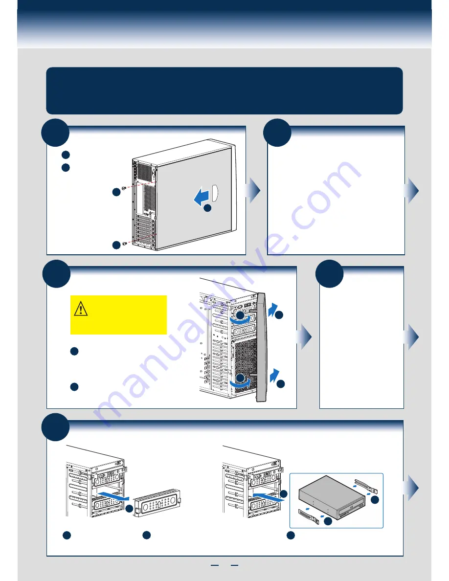
Remove the Bezel Assembly
A
B
A
A
B
B
At a 40-degree angle, push the bezel
assembly away from the chassis.
Release the two plastic tabs on the left side
of the bezel assembly to disengage the
tabs, and rotate the bezel assembly no
more than 40 degrees outward.
CAUTION: Do not rotate the bezel
assembly more than 40° or you will
damage the bezel hooks at the
right side of the bezel assembly.
4
Install Hard
Drive
See
Hard Drive Installation
Section (
Page 7
) for your
Hard Drive Installation.
5
Install Tool-less CD-ROM or DVD-ROM Drive
A
A
B
Attach slides to the DVD or CD-ROM drive by pressing
the slides firmly into the side dimples on the DVD or
CD-ROM drive.
Remove an EMI shield.
C
Insert the drive/slide assembly into the
device bay until the slides lock into place.
C
B
B
General Installation Process
Remove the Side Cover
B
Remove the screws.
A
Note:
A non-skid surface or
a stop behind the
chassis may be
needed to prevent the
chassis from sliding
on your work surface.
Slide the side cover
back and lift the cover
outward to remove it.
A
A
B
1
The installation instructions in this section are for general components of Intel® Server Chassis
P4000S family, but the illustrations are based on the Intel® Server Chassis P4304XXSFCN.
2
Install Server Board
• If the server board is pre-installed, please follow the
instructions in
Processor, Heat Sink, Memory
Installation
section (
Page 5
) to install the
Processor(s), Heat Sink(s) and Memory.
Return to this section when finished.
• If the server board is to be installed, please use the
bumpers
,
standoffs
and
mounting screws
that
came with your chassis, and open the Intel
®
Server
Board box, then follow the instructions in the enclosed
Intel
®
Server Board
Quick Start User’s Guide
for
server board installation and back panel I/O shield
installation.
Return to this section when finished.
Summary of Contents for P4304BT series
Page 4: ......
Page 16: ...G23642 001...


