3
General Installation Process
The installation instructions in this section are for general components of Intel® Server System
P4000MCP family, but the illustrations are based on the Intel® Server System P4308CP4MHEN.
Minimum Hardware Requirements
■
Processor
■
Heat Sink
■
Memory
■
Hard Disk Drives
■
Power
■
Air Duct
To avoid integration difficulties and possible damage to your system,
make sure you have components from each category below.
1
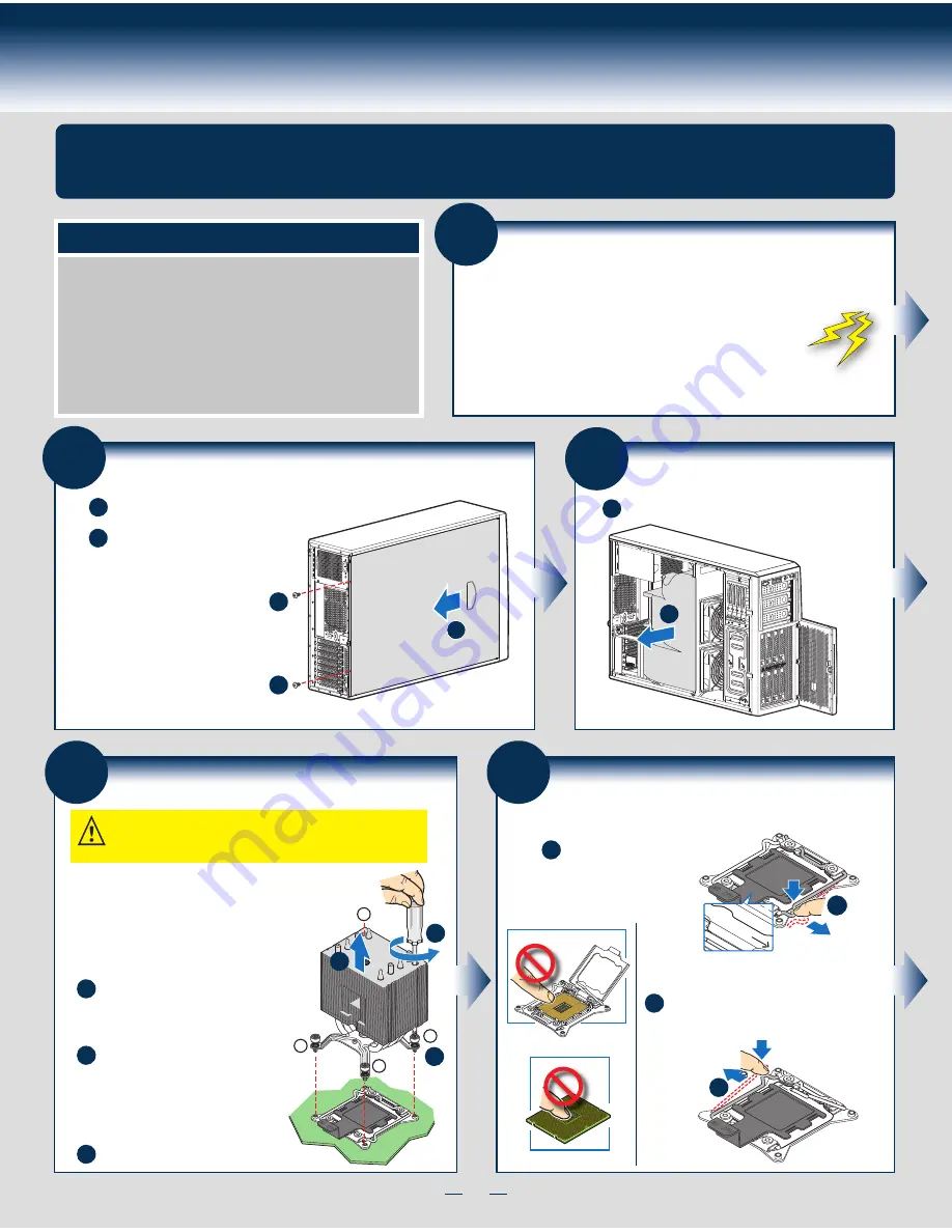
Preparing the System
Observe normal ESD (Electrostatic Discharge) procedures.
Place your Intel
®
Server System on a flat anti-static
surface to perform the following integration procedures.
Observe ESD procedures before reaching inside to make
server board connections or install components.
A
3
Remove the Air Duct
A
Remove the air duct.
4
Remove Processor Heatsink(s)
The heatsink is attached to the server
board / processor socket with captive fasteners.
Lift the heatsink straight up.
A
C
Proceed to screw 2 and loosen it by
giving it two rotations and stop.
Similarly, loosen screws 3 and 4.
Repeat steps A and B by giving each
screw two rotations each time until
all screws are loosened.
Using a #2 Phillips* screwdriver,
start with screw 1 and loosen it
by giving it two rotations and stop.
(IMPORTANT: Do not fully loosen.)
B
CAUTION: The heatsink has thermal interface material (TIM) on
the underside of it. Use caution so that you do not damage the
thermal interface material.
Use gloves to avoid sharp edges.
Using a #2 Phillips* screwdriver, loosen the four
screws located on the heatsink corners in a
diagonal manner using the following procedure:
OPEN
1st
CLOS
E 1st
NO CP
U
Processor
Soc
ket
2
3
1
4
A
B
C
5
Install the Processor(s)
CLOS
E 1st
OPEN
1st
REM
OVE
REM
OVE
OPEN
1st
A
NO CP
U
OPEN
1st
CLOS
E 1st
B
NO CP
U
A. Open the Socket Lever
A
B
Repeat step A to release
the lever on the other
side.
Push down the lever
handle on the
OPEN 1st
side and away from the
socket to release it.
NOTE: Release
the levers in the
order as shown.
Remove the Side Cover
B
Remove the screws.
A
Note:
A non-skid surface or a
stop behind the chassis
may be needed to prevent
the chassis from sliding on
your work surface.
Slide the side cover back and lift
the cover outward to remove it.
A
A
B
2
Summary of Contents for P4208CP4MHGC
Page 2: ...This page is intentionally left blank...
Page 17: ...G43150 001...


