background image

M440LX Server System Product Guide

91

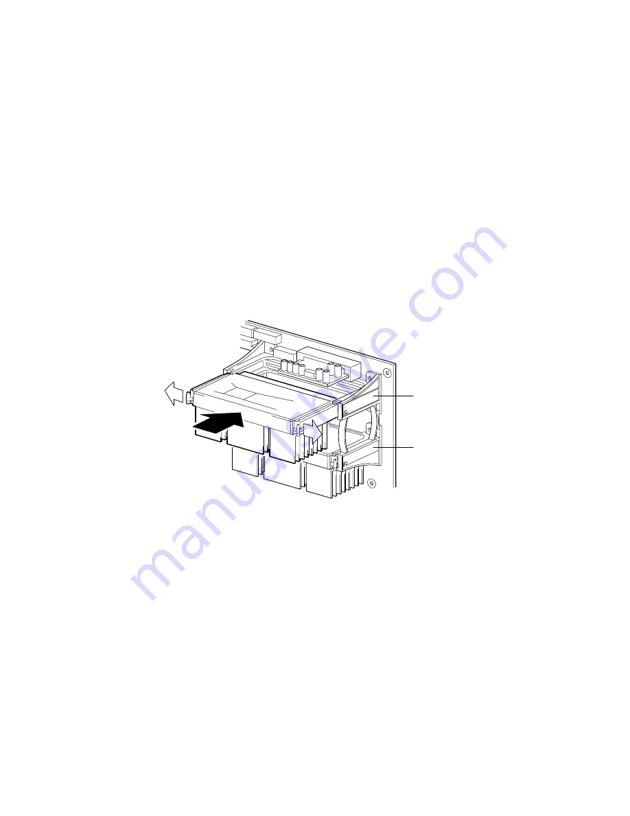
Installing a Pentium II Processor

See Figure 4-7.

1.  Observe the warnings and cautions on page 3, “Safety Guidelines.”

2.  Remove the left side cover (page 80).

3.  Being careful not to touch the components or gold edge connectors on

the processor module, remove it from its protective wrapper and place
it heat-sink side down on a nonconductive, static-free surface.

4.  Record the module serial number in your equipment log.

5.  Press the locking tabs inward until they remain retracted.

6.  Hold the module by its top edge or upper corners, and firmly press it

into the connector (Figure 4-7) on the system board.  Press the locking
tabs outward so they engage the support bracket.

OM05775

CPU1

CPU0

Figure 4-7.  Installing a Pentium II Processor

7.  Replace the left side cover (page 81).

8.  Run the SCU to configure the system.  For information about running

the utility, see Chapter 3, "Configuring The System."

Summary of Contents for MB440LX

Page 1: ...Intel MB440LX System Installation Guide...

Page 2: ...of any kind with regard to this material including but not limited to the implied warranties of merchantability and fitness for a particular purpose Intel assumes no responsibility for any errors tha...

Page 3: ...d metal surface when handling components Warnings and Cautions These warnings and cautions apply whenever you remove the side cover of the server to access components inside the server Integration of...

Page 4: ...ction by wearing an antistatic wrist strap attached to chassis ground of the server any unpainted metal surface when handling components HANDLING BOARDS AND MODULES Boards and modules can be extremely...

Page 5: ...x y Two or three key names separated by plus signs indicate multiple key entries For example Ctrl Alt Del means hold down Ctrl and Alt and press Del Three squares mark the end of a chapter The specia...

Page 6: ...1 6 Your Chapter Title Goes Here...

Page 7: ...Video Blanking 28 Power System 28 Server Cooling 28 Peripheral Drive Bays 29 3 5 inch User Accessible Diskette Drive Bay 29 5 25 inch User Accessible Drive Bays 29 3 5 inch Hot docking Drive Bays 29...

Page 8: ...kettes 47 3 Configuring The System Configuration Utilities 49 Power on Self Test 50 When to Use the System Configuration Utility 51 How to start the SCU 52 System Board Settings Field Descriptions 53...

Page 9: ...the Plastic Front Cover 84 Removing the Snap in Plastic Peripheral Bay Cover 86 Replacing the Snap in Plastic Peripheral Bay Cover 87 Board Set 88 Removing the Termination Board 88 Installing a Voltag...

Page 10: ...ackplane 129 SCSI Hot docking Backplane 130 Removing a Hot docking Backplane 130 Installing a Hot docking Backplane 130 5 SCSI Backplane and Drives Hot swapping and Configuring Warnings and Cautions 1...

Page 11: ...165 Remote Sense Connections 165 Load Share Connection 165 Output Power Connections 165 Power Good Circuit 166 VA Monitor Circuit 166 I C Communication Circuit 166 System Current Monitor 167 Power Su...

Page 12: ...rver System Board 185 System Board Layout 186 System Board Connector Locations 187 Power Connector 188 Auxiliary Power Connector 188 I2 C Connector 188 Control Panel Connector 189 Diskette Drive Port...

Page 13: ...stem Cooling Fans Do Not Rotate Properly 208 No Characters Appear on Screen 209 Characters Are Distorted or Incorrect 209 Incorrect or no Beep Codes 210 Diskette Drive Activity Light Does Not Light 21...

Page 14: ...81 4 2 Top Cover 83 4 3 Plastic Front Cover 85 4 4 Snap in Plastic Peripheral Bay Cover 86 4 5 Removing a Termination Board 89 4 6 Installing a Voltage Regulator Module 90 4 7 Installing a Pentium II...

Page 15: ...e Power Share Backplane 127 4 27 Power Share Backplane Connectors 128 4 28 Removing a Hot docking Backplane 131 5 1 Hard Disk Drive and Plastic Carrier 135 5 2 Installing a Hard Disk Drive 137 5 3 SCS...

Page 16: ...16 Contents...

Page 17: ...our SDRAM DIMM sockets for 512 MB of memory RPX module with one SIMM socket for RAID applications The chassis contains a 3 5 inch diskette drive a CD ROM drive and depending on the system configuratio...

Page 18: ...the processors Three integrated power supply fans cool and circulate air through the power supply side of the system if it contains only one or two power supplies an additional fan provides cooling a...

Page 19: ...seven 8 bit narrow SCSI devices Two Symbios wide SCSI controllers for connecting a mixture of fifteen 8 bit narrow and 16 bit wide SCSI devices to the controller maximum of seven 8 bit narrow SCSI de...

Page 20: ...y bays with up to three 360 watt power supplies depending on the configuration One vertical bay that contains a diskette drive Three standard 5 25 in bays for removable media devices a CD ROM drive is...

Page 21: ...s in and out of the system Both removable side covers are attached to the chassis with three screws They provide proper airflow and easy access to the system board and power supplies These covers can...

Page 22: ...4 5 Figure 1 2 Back Right Side View 1 Left side cover 2 I O panel 3 Knock out slots for external SCSI connectors 4 Expansion slots 5 Power supplies 6 SCSI hot docking bay 7 SCSI hot docking backplane...

Page 23: ...he hot docking bay Green power LED when lit indicates the presence of DC power in the system The LED goes out when the power is turned off or the power source is disrupted Power button when pressed tu...

Page 24: ...ette drive activity LED 2 Diskette drive ejector button 3 CD ROM open close button 4 CD ROM power LED 5 CD ROM volume control 6 CD ROM headphone jack 7 Reset button 8 Power supply failure LED 9 Fan fa...

Page 25: ...nals to the system board Software on the system board intercepts these signals and alerts the user to unauthorized activity Security with the Setup utility Set administrative and user passwords Set se...

Page 26: ...26 Chapter 1 Server Description OM05793 Figure 1 4 Security Padlocks...

Page 27: ...system boots from the CD ROM drive or diskette drive and disables the secure mode If there is no CD in the CD ROM drive or diskette in drive A the system boots from drive C and automatically goes int...

Page 28: ...accepts these input voltage ranges 100 120 VAC at 50 60 Hertz Hz 7 7 A maximum current 200 240 VAC at 50 60 Hz 4 4 A maximum current If a single power supply fails in a redundant power system the yel...

Page 29: ...hat consume up to 11 watts of power and run at a maximum ambient temperature of 55 C You can install an additional hot docking backplane in the lower hot docking bay for five more drives However if yo...

Page 30: ...1 and JBOD Support for hot spares hot plugs and user selectable rebuild rate Support for multiple rebuilds across separate arrays and multiple consistency checks Write back cache support with battery...

Page 31: ...rray SVGA controller that is fully compatible with these video standards CGA EGA Hercules Graphics MDA and VGA The standard server configuration comes with 512 KB of onboard video memory allowing pixe...

Page 32: ...decimal Mode Number Bits Per Pixel Colors number palette size Resolution Pixel Frequency MHz Horizontal Frequency kHz Vertical Frequency Hz 0 1 4 16 256K 360 X 400 14 31 5 70 2 3 4 16 256K 720 X 400 2...

Page 33: ...768 65 48 3 60 5D 8 16 256K 1024 X 768 75 56 70 5D 8 16 256K 1024 X 768 78 7 60 75 5F 8 256 256K 640 X 480 25 31 5 60 5F 8 256 256K 640 X 480 31 5 37 5 75 60 8 256 256K interlaced 1024 X 768 44 9 35...

Page 34: ...rrow SCSI controller integrated as a PCI bus master You can connect a maximum of seven narrow SCSI devices to this controller The SCSI controllers provide active negation outputs controls for external...

Page 35: ...wer supply voltage levels Monitors then processor thermal trip and internal error signals Monitors the fan sensors Manages two I2C thermal sensors located near each processor Manages fault resilient b...

Page 36: ...mentation conforms to the Multiprocessor Specification Version 1 4 Memory Module The memory module has eight DIMM sockets The module supports from 16 MB to 1 GB of extended data out EDO ECC memory 3 3...

Page 37: ...vertical drive bay that contains a diskette drive Three standard 5 25 inch drive bays a CD ROM drive is installed in the top bay Two bays each with space for five 3 5 inch SCSI hard disk drives a SCS...

Page 38: ...hree power supplies A second power supply provides additional power or acts as an redundant power supply depending on the system configuration The powershare upgrade kit is not required to upgrade fro...

Page 39: ...t a site Install the Pentium II processor Install the memory module Set the line voltage selector switch and check the power cord s Connect input and output devices Turn on the server and create insta...

Page 40: ...ounded outlet clean and dust free well ventilated and away from sources of heat spacious enough to provide sufficient room behind and around the server so that you can remove AC power from it by unplu...

Page 41: ...ve humidity noncondensing at 35 C 95 F Shock Nonoperating Operating 20 g 11 msec 1 2 sine 2 0 g 11 msec 1 2 sine Altitude Nonoperating Operating To 50 000 ft 15 240 m To 10 000 ft 3 048 m Acoustic noi...

Page 42: ...the server in the event you decide to move it to another site Installing the Pentium II Processor The server is shipped without the processor module installed on the system board Turn to Chapter 4 Wo...

Page 43: ...ed technical person Keyboard Insert the cable connector of a PS 2 compatible keyboard into the 6 pin miniature Deutsche Industrie Norm DIN connector on the system back panel The keyboard port is overc...

Page 44: ...ure 2 1 Server I O Panel 1 PS 2 compatible keyboard connector 2 PS 2 compatible mouse connector 3 PS 2 compatible serial port 1 COM1 connector 4 PS 2 compatible parallel port LPT1 connector 5 Super VG...

Page 45: ...system power supply must be an IEC 320 sheet C13 type female connector In Europe the cord must be less than 4 5 meters 14 76 feet long and it must be flexible HAR harmonized or VDE certified cordage...

Page 46: ...r on light on the front panel is lit After a few seconds POST begins See Power on Self Test OM05780 3 1 2 Figure 2 2 Power and Reset Buttons 1 Power button 2 Reset button 3 Power on light LED Power on...

Page 47: ...Software Diskettes 1 Insert the Configuration Software CD in the CD ROM Drive 2 Reboot the system 3 When POST completes the server boots from the CD and displays the CD ROM menu 4 Follow the menu pro...

Page 48: ...48 Chapter 2 Installing The System...

Page 49: ...CU is on the Configuration Software CD shipped with the system See Chapter 2 Installing The System for instructions on creating an SCU diskette See page 51 BIOS Setup Utility is stored in both flash m...

Page 50: ...most installed peripheral devices During the memory test the POST displays the amount of memory that it is able to access and test Depending on the amount installed on the memory module the test may...

Page 51: ...However some ISA add in boards do come with a CFG file The SCU uses the information provided by the OVL and CFG files configuration registers NVRAM and the information that you enter to specify a sys...

Page 52: ...e in the directory type AMISCU and press Enter From diskette after installing the operating system Insert the System Configuration Utility Disk in drive A At the MS DOS prompt type a and press Enter t...

Page 53: ...on MP Spec Version MP Spec V1 1 MP Spec V1 4 System Processor Modules Processor 1 Pentium II Processor at XXXMHz Display only Processor 2 Pentium II Processor at XXXMHz Display only Memory Subsystem G...

Page 54: ...able On Board IDE Controller Enable Disable Onboard Communications Devices Serial Port 1 Configuration Port 1 Disable 3E8h IRQ 4 3E8h IRQ 3 3F8h IRQ 4 3F8h IRQ 3 2E8h IRQ 4 2E8h IRQ 3 2F8h IRQ 4 2F8h...

Page 55: ...Extended Capabilities Parallel Port DMA 3 Floppy Drive Subsystems Group Floppy drive A Options 3 5 inch 1 44 1 25 MB drive 5 25 inch 360 KB drive 5 25 inch 1 2 MB drive 3 5 inch 720 KB drive 3 5 inch...

Page 56: ...ndard CHS Logical Block Addressing Transfer Mode Standard PIO 1 PIO 2 PIO 3 PIO 4 IDE Configuration Primary Slave Configuration Selection None User Auto CD IDE Drive Options Primary Slave If the Confi...

Page 57: ...Subsystem Group Typematic Speed 30 CPS 26 CPS 21 CPS 18 CPS 13 CPS 10 CPS 6 CPS 2 CPS Typematic Delay 250 mS Delay 500 mS Delay 750 mS Delay 1000 mSec Delay Mouse Control Option Mouse Enabled Mouse Di...

Page 58: ...n Password Menu Enter Password XXXXX Verify Password XXXXX User Password Option Password Menu Enter Password XXXXX Verify Password XXXXX Other Security Subsystem Options Hot Key Option Disable Enable...

Page 59: ...40LX Server System Product Guide 59 SCSI ROM BIOS Options Group Embedded SCSI Option ROM Scan Enable Disable Management Subsystem Group System Management Mode Disable Enable Event Logging Disable Enab...

Page 60: ...Setup to specify the correct configuration You can run the Setup utility with or without an operating system being present Since values entered using the Setup utility are overwritten when you run th...

Page 61: ...Submenu Hard Drive Submenu Exit Menu Use the following keys to navigate through the menus and submenus Press To F1 Get help about an item ESC Go back to a previous item Enter Select an item Return to...

Page 62: ...r each followed by Enter Diskette A Disabled 360 KB 5 1 2 MB 5 720 KB 3 1 44 1 25 MB 3 2 88 MB 3 Diskette B Disabled 360 KB 5 1 2 MB 5 720 KB 3 1 44 1 25 MB 3 2 88 MB 3 Primary IDE Master Press Enter...

Page 63: ...Sectors Determines the number of sectors per block for multiple sector transfers LBA Mode Control Disabled Enabled Disables Enables Logical Block Access 32 Bit I O Disabled Enabled Disables Enables 32...

Page 64: ...u Feature Option Comments Numlock Auto On Off Selects the state for NumLock at power on Key Click Disabled Enabled Keyboard auto repeat rate 30 sec 26 7 sec 21 8 sec 18 5 sec 13 3 sec 10 sec 6 sec 2 s...

Page 65: ...nfiguration Press Enter See page 66 PCI configuration Submenu Integrated Peripheral Configuration Press Enter See page 68 Integrated Peripheral Configuration Submenu Use Multiprocessor Specification 1...

Page 66: ...er See page 68 PCI Device Submenu PCI Device Slot 2 Press Enter See page 68 PCI Device Submenu PCI Device Slot 3 Press Enter See page 68 PCI Device Submenu PCI Device Slot 4 Press Enter See page 68 PC...

Page 67: ...ption Comments Option ROM Scan Enabled Disabled Narrow SCSI Latency Timer Default 0020h 0040h 0060h 0080h 00A0h 00C0h 00E0h Wide SCSI A Latency Timer Default 0020h 0040h 0060h 0080h 00A0h 00C0h 00E0h...

Page 68: ...de SCSI A Latency Timer Default 0020h 0040h 0060h 0080h 00A0h 00C0h 00E0h Integrated Peripherals Submenu Feature Option Comments Serial port A Disabled Enabled Auto PnP OS Serial port A Base I O addre...

Page 69: ...E8 Serial port B Interrupt IRQ 3 IRQ 4 Parallel port Disabled Enabled Auto PnP OS Parallel port Mode Output only Bi directional EPP ECP Parallel port Base I O address 378 278 Parallel port Interrupt I...

Page 70: ...haracters See page 71 Password Menu Set Administrative Password Press Enter Supervisor password controls access to the setup utility Password may be from one to seven characters See page 71 Password M...

Page 71: ...ecure mode Secure Mode Boot Disabled Enabled Enabled lets the system boot before a password is required However the keyboard and mouse remain locked until the user password is entered Video Blanking D...

Page 72: ...and retest all processors on the next boot System Management Submenu Feature Option Comments System Management Mode Disabled Enabled Loads the embedded Server Management firmware System Event Logging...

Page 73: ...ddress field is set Flow Control No Flow Control CTS RTS XON XOFF CTS RTS CD Uses the specified flow control for console redirection Cannot be set unless the COM Port Address field is set Boot Menu Fe...

Page 74: ...the list 2 Hard Drive 3 ATAPI CD ROM Drive 4 Diagnostic Boot Hard Drive Submenu These options may change depending on the system configuration Feature Option Comments 1 Hard Drive Select a device and...

Page 75: ...without saving Setup data to CMOS Load Setup Defaults Press Enter Loads and displays the default Setup data Load Custom Defaults Press Enter Loads and displays settings from Custom Defaults Save Cust...

Page 76: ...he server Running the SCSI Utility 1 When this message appears on the video monitor Press Ctrl C to run SCSI Utility 2 Press Ctrl C to run this utility When it appears choose the host adapter that you...

Page 77: ...nstructions on creating Video diskettes see Chapter 2 Installing The System To install these video drivers do this 1 Fully configure the system This may include adding video DRAM buffer memory applica...

Page 78: ...78 Chapter 3 Configuring The System...

Page 79: ...f the system If you installed a padlock unlock and remove it Warnings and Cautions Before you remove the covers observe the warnings and cautions provided for your safety on page 3 Safety Guidelines S...

Page 80: ...tal peripheral bays You must remove both side covers and the top cover before you can remove the front cover The snap in plastic peripheral bay cover provides access to the 5 25 inch horizontal periph...

Page 81: ...ide the chassis 2 Ensure that add in boards are firmly seated in their respective slots retaining brackets are firmly secured with screws tightened to 6 0 inch pounds and interior cables are properly...

Page 82: ...y into the system insert a padlock through the metal loop protruding through the slot in the back of the side cover and lock it 6 Connect all external cables and the power cord s to the system Removin...

Page 83: ...rly connected 3 Position the top cover Figure 4 2 over the chassis so that the tabs along the front of the cover align with the slots in the top edge of the chassis 4 Slide the cover toward the front...

Page 84: ...surface so that it doesn t get scratched Replacing the Plastic Front Cover See Figure 4 3 1 Insert the plastic T shaped tabs on the bottom front cover into the T shaped notches along bottom of the cha...

Page 85: ...M440LX Server System Product Guide 85 OM05786 1 2 3 Figure 4 3 Plastic Front Cover 1 Screw 2 Plastic front cover 3 Plastic tab...

Page 86: ...skette drive Then push the tab toward the front of the system until you can grasp the lower right corner of the cover CAUTION Do not try to remove the snap in peripheral bay cover by inserting a screw...

Page 87: ...tic front panel 2 Push the top right corner of the plastic cover toward the chassis with an inward twisting motion to insert the top flexible tab in the slot above the 3 5 inch diskette drive 3 Gently...

Page 88: ...e Do not slide the module over any surface If you are upgrading a one processor system with a second processor you must install a voltage regulator and remove the termination board from the CPU1 slot...

Page 89: ...idelines 2 Remove the left side cover page 80 3 Being careful not to touch the components or connector on the voltage regulator module remove it from its protective wrapper and place it on a nonconduc...

Page 90: ...90 Chapter 4 Working Inside Your System OM05774 3 1 2 Figure 4 6 Installing a Voltage Regulator Module 1 Module 2 Connector 3 Lock Tab...

Page 91: ...nonconductive static free surface 4 Record the module serial number in your equipment log 5 Press the locking tabs inward until they remain retracted 6 Hold the module by its top edge or upper corner...

Page 92: ...c free surface Installing the Memory Module See Figure 4 8 1 Observe the warnings and cautions on page 3 Safety Guidelines 2 Remove the left side cover page 80 3 Remove the rail 4 Being careful not to...

Page 93: ...oduct Guide 93 OM05760B 1 3 2 Figure 4 8 Installing the Memory Module 1 System board 2 Connector 3 Module 8 Run the SCU to configure the system For information about running the utility see Chapter 3...

Page 94: ...ve static free surface 6 Install the rail Installing the RPX Module See Figure 4 9 1 Observe the warnings and cautions on page 3 Safety Guidelines 2 Remove the left side cover page 80 3 Remove the RPX...

Page 95: ...Product Guide 95 OM05760A 1 3 2 Figure 4 9 Installing the RPX Module 1 System board 2 Connector 3 Module 9 Run the SCU to configure the system For information about running the utility see Chapter 3 C...

Page 96: ...emove the left side cover page 80 3 Remove the RPX rail 4 Holding the module by its top edge or upper corners carefully rock it back and forth until the edge connector pulls free 5 Unplug the RPX batt...

Page 97: ...m board by installing add in boards that draw excessive current For expansion slot current limitations see Chapter 7 Power System Add in boards can be extremely sensitive to ESD and always require car...

Page 98: ...ling an Add in Board See Figures 4 10 4 11 and 4 12 1 Observe the warnings and cautions on page 3 Safety Guidelines 2 Remove the left side cover page 80 3 Remove and save the expansion slot screw and...

Page 99: ...d foot of the board retaining bracket must fit into the mating slot in the expansion slot frame 8 Align the rounded notch in the retaining bracket with the threaded hole in the expansion slot frame Th...

Page 100: ...100 Chapter 4 Working Inside Your System OM04639 Figure 4 11 Installing an ISA Add in Board Component side Up...

Page 101: ...M440LX Server System Product Guide 101 OM04640 Figure 4 12 Installing a PCI Add in Board Component side Down...

Page 102: ...pper corners carefully rock it back and forth until the edge connector pulls free Make sure that you do not scrape the board against other components 6 Store the board in an antistatic protective wrap...

Page 103: ...ures 4 13 and 4 14 1 Observe the warnings and cautions on page 3 Safety Guidelines 2 Remove the right side cover page 80 3 Disconnect the power and signal cables from the diskette drive 4 Remove the s...

Page 104: ...104 Chapter 4 Working Inside Your System OM05769 1 2 3 4 Figure 4 13 Removing the Diskette Drive 1 Signal cable 2 Power cable 3 Screw 4 Drive and carrier assembly...

Page 105: ...M05791 1 2 3 Figure 4 14 Diskette Drive and Carrier Assembly 1 Screw 2 Carrier 3 Diskette drive Installing a Diskette Drive See Figures 4 13 and 4 14 1 Remove the 3 5 inch diskette drive from its prot...

Page 106: ...gnal cable must face toward the center of the drive 9 Replace the right side cover page 81 10 Run the SCU to specify that the diskette drive is installed in the system For information about running th...

Page 107: ...it on a smooth surface so that it doesn t get scratched 4 Remove the screws and filler panel and set them aside OM05315 Figure 4 15 Filler Panels 5 Push the tab on the left side of the EMI metal shiel...

Page 108: ...108 Chapter 4 Working Inside Your System OM04647 Figure 4 16 Removing the EMI Shield 9 Using two screws of the appropriate size and length not supplied attach each plastic slide rail to the device...

Page 109: ...e 4 17 Snap in Plastic Slide Rails 1 Tape drive or other device 2 Tab 3 Screw 4 Slide rail 10 Position the device so that the plastic slide rails on each side of it engage in the bay guide rails Push...

Page 110: ...11 Replace the snap in plastic peripheral bay cover top cover and both side covers 12 This step is optional If you installed a SCSI CD ROM drive run the Symbios SCSI utility to enable BIOS support fo...

Page 111: ...ng plastic snap in rails attached to the drive toward each other carefully slide the drive forward out of the bay and place it on an antistatic surface 6 Remove and save the four screws and the two sn...

Page 112: ...lling system board components that are located near processors The following warning and translations are required by specific certifying agencies to be printed immediately adjacent to the procedure f...

Page 113: ...or equivalent under the plastic tab on the snap on plastic retainer Gently lift up and pull back on the retainer to remove it from the lithium battery socket 4 Remove the battery from its socket 5 Dis...

Page 114: ...114 Chapter 4 Working Inside Your System OM05791A 1 2 3 Figure 4 19 Lithium Back up Battery...

Page 115: ...of the system until it clears the snap on standoff 5 Label and disconnect all the cables connected to the front panel board 6 Remove the board from the system and place it on an antistatic foam pad o...

Page 116: ...116 Chapter 4 Working Inside Your System OM05268 Figure 4 20 Removing the Front Panel Board...

Page 117: ...h a tachometer signal or an approved fan Replace a failed blower with the same type See Chapter 9 I O Ports and Connectors Contact your sales representative or dealer for a list of approved fans and b...

Page 118: ...118 Chapter 4 Working Inside Your System OM05278 Figure 4 21 Front Panel Fans...

Page 119: ...40LX Server System Product Guide 119 6 Remove the fan from the plastic housing by pushing the inner flexible tabs on the housing away from the fan Save the housing OM05277 Figure 4 22 Front Fan Assemb...

Page 120: ...housing 3 Press down on the fan until the inner flexible plastic tabs on the housing snap into place on the fan Make sure you do not pinch the cable between the housing and the fan 4 Position the pla...

Page 121: ...e 4 Press the top outer flexible tab on the plastic housing and fan assembly toward the fan until you can pull the tab through the slot in the chassis 5 Pull the top of the assembly toward the hot doc...

Page 122: ...he finger guard to the fan Set the screws and finger guard aside 8 Place the assembly fan side up on a flat surface Remove the fan from the plastic housing by pushing the inner flexible tabs on the ho...

Page 123: ...plastic tabs on the housing snap into place on the fan Make sure you do not pinch the cable between the housing and the fan 4 Place the assembly fan side down on a flat surface Attach the finger guar...

Page 124: ...r supply fails in a system with a power share board the yellow power supply failure LED on the front panel starts flashing Generally a failed power supply can be replaced while the system is running R...

Page 125: ...Replacing a Power Supply See Figure 4 25 1 Observe the warnings and cautions on page 3 Safety Guidelines 2 Slide the power supply through the back of the system 3 Attach the power supply to the syste...

Page 126: ...t inside the power share backplane There are no user serviceable parts inside it servicing should be done only by technically qualified personnel Removing the Power Share Backplane See Figures 4 26 an...

Page 127: ...M440LX Server System Product Guide 127 OM05771 Figure 4 26 Removing the Power Share Backplane...

Page 128: ...nnectors 1 Input from top power supply 2 Input from middle power supply if present 3 Input from bottom power supply if present 4 Factory configured jumper 5 Nonremovable cover 6 Output to system perip...

Page 129: ...e over the snap in standoffs and threaded standoffs on the inside chassis wall 4 Push the backplane toward the chassis wall until it snaps onto the snap in standoffs 5 Insert the screws through the mo...

Page 130: ...he back of the hot docking bay and set them aside 6 Remove the backplane from the system and place it on an antistatic surface Installing a Hot docking Backplane See Figure 4 28 1 Observe the warnings...

Page 131: ...oduct Guide 131 OM05269 1 2 3 4 5 6 Figure 4 28 Removing a Hot docking Backplane 1 Fan cable if present 4 Front panel cable 2 Peripheral power connector 5 SCSI signal cable 3 Peripheral power connecto...

Page 132: ...132 Chapter 4 Working Inside Your System...

Page 133: ...mended Hot docking Bays The plastic front door covers a removable metal door that is secured to the chassis with two screws Plastic drive carriers for 3 5 inch wide by 1 inch high drives allow easy ho...

Page 134: ...es in your system Installing differential SCSI drive types can result in electrical damage to the system board and the peripherals CAUTION ELECTROSTATIC DISCHARGE ESD AND ESD PROTECTION ESD can damage...

Page 135: ...ntistatic surface 2 Record the drive model and serial number in your equipment log 3 Orient the drive so the connector is near the top surface of the drive and place it on an antistatic surface 4 Plac...

Page 136: ...arrier locking tab up and drive assembly so it engages the hot docking bay guide rails 5 Gently push the drive into the bay until it docks with the backplane connector and snaps into place 6 Gently cl...

Page 137: ...M440FX Server System Product Guide 137 OM06470 1 2 Figure 5 2 Installing a Hard Disk Drive...

Page 138: ...Check the two banks of yellow LEDs on the front panel to determine which drive is bad Grasp the plastic drive carrier and pull it toward you to disengage the drive connector from the backplane connec...

Page 139: ...rough cables connected to the two power connectors The drives get their control signals and power from the SCA connectors on the backplane The fault indicators on the front panel indicate failure stat...

Page 140: ...he backplane assumes it is operating in an external peripheral bay in a peripheral expansion chassis This option is not available SCSI ID Configuration Options The SCSI chip on the hot docking backpla...

Page 141: ...t side cover as described in Chapter 4 Working Inside Your System 4 The jumpers are parallel with the backplane surface as shown in Figure 5 3 Looking into the right side of the system between the bac...

Page 142: ...nd Configuring OM05270 1 2 5 3 4 6 7 8 9 1 2 3 1 2 3 1 2 3 1 2 3 J10 J9 J8 J7 Figure 5 3 SCSI Backplane 1 SCSI ID B J10 2 SCSI ID A J9 3 Internal external J8 4 Normal operation J7 5 SCSI drive 4 6 SCS...

Page 143: ...7 TERMPWR 51 TERMPWR 18 TERMPWR 52 TERMPWR 19 RESERVED 53 RESERVED 20 34 GND ground 54 GND ground 35 DB 12_L 55 ATN_L 36 DB 13_L 56 GND ground 37 DB 14_L 57 BSY_L 38 DB 15_L 58 ACK_L 39 DB P1_L 59 RST...

Page 144: ...B 2_L 7 DB 11_L 27 DB 1_L 8 DB 10_L 28 DB 0_L 9 DB 9_L 29 DB P_L 10 DB 8_L 30 DB 15_L 11 I O_L 31 DB 14_L 12 REQ_L 32 DB 13_L 13 C D_L 33 DB 12_L 14 SEL_L 34 36 5 V 15 MSG_L 37 SYNC 16 RST_L 38 MTRON_...

Page 145: ...wer connectors are 4 pin shrouded plastic connectors with mechanical keying OM04656 1 2 3 4 Pin Signal 1 12 V 2 Ground 3 Ground 4 5 V Fan Connector This connector provides power to the fan below the t...

Page 146: ...controls them OM04669 1 Pin Name Description 1 GND Electrical ground 0V 2 I2C_SDA I 2 C SDA Serial Data 3 GND Electrical ground 0V 4 I2C_SCL I 2 C Serial Clock 5 RFU Reserved for future use 6 FAULT1_...

Page 147: ...s and cautions provided for your safety on page 3 Safety Guidelines System integration should be done by technically qualified personnel Tools and Supplies You Need Phillips cross head screwdriver 1 b...

Page 148: ...n normally It detects all double bit errors but does not correct them it also detects all three bit and four bit adjacent errors in a DRAM nibble but does not correct them When one of these multiple b...

Page 149: ...M440LX Server System Product Guide 149 OM05785A DIMM 0 J1 DIMM 1 J2 DIMM 2 J3 DIMM 3 J4 DIMM 4 J5 DIMM 5 J6 DIMM 6 J7 DIMM 7 J8 Figure 6 1 Memory Module...

Page 150: ...ction 0000_0000h 0007_FFFFh 512 KB DOS region base system memory fixed 0008_0000h 0009_FFFFh 128 KB ISA window memory 000A_0000h 000B_FFFFh 128 KB PCI ISA Video or SMM 000C_0000h 000D_FFFFh 128 KB Add...

Page 151: ...32 MB DIMM 4M x 72 32 MB 64 MB DIMM 8M x 72 64 MB 128 MB DIMM 16M x 72 128 MB Table 6 2 Sample DIMM Size Combinations Banks Filled 0 J1 1 J2 2 J3 3 J4 4 J5 5 J6 6 J7 7 J8 Total Memory 8 8 MB 8 16 24...

Page 152: ...ty Guidelines 2 Remove the left side cover and memory module as described in Chapter 4 Working Inside Your System 3 Hold the module only by its edges being careful not to touch its components or gold...

Page 153: ...53 OM05784A DIMM 0 J1 DIMM 1 J2 DIMM 2 J3 DIMM 3 J4 DIMM 4 J5 DIMM 5 J6 DIMM 6 J7 DIMM 7 J8 1 2 Figure 6 2 DIMM Orientation 1 Bank 0 J1 2 Bank 1 J2 3 Bank 2 J3 4 Bank 3 J4 5 Bank 4 J5 6 Bank 5 J6 7 Ba...

Page 154: ...so on with the last one in bank 7 socket J8 9 Install the memory module and the left side cover as described in Chapter 4 Working Inside Your System 10 Connect all external cables and the power cord s...

Page 155: ...e it on an antistatic surface 4 Starting with the first DIMM filled socket closest to the top edge of the module remove the DIMMs one at a time CAUTION Use extreme care when removing a DIMM Too much p...

Page 156: ...Inside Your System 9 Connect all external cables and the power cord s to the system 10 Turn on the monitor and then the system 11 Run the System Configuration Utility SCU to configure the system and t...

Page 157: ...rnings and cautions on page 3 Safety Guidelines 2 Remove the left side cover as described in Chapter 4 Working Inside Your System 3 Remove the 256 K x 16 60 ns DRAM from its protective package and ali...

Page 158: ...ARNING Installing the video DRAM chip incorrectly in the socket could produce an extremely high case temperature destroy the chip and possibly the system board Do not touch the chip after such an occu...

Page 159: ...Clock RTC 0080h 0081h BIOS Timer 0080h 008Fh DMA Low Page Register 0092h System Control Port A PC AT control Port 00A0h 00BFh Interrupt Controller 2 00C0h 00DFh DMA Controller 2 00F0h Clear NPX error...

Page 160: ...7h DMA Controller 2 Extended Mode Register 04D8h 04DFh Reserved 04E0h 04FFh DMA Channel Stop Registers 0678h 067Ah Parallel Port ECP 0778h 077Ah Parallel Port ECP 07BCh 07BEh Parallel Port ECP 0800h 0...

Page 161: ...rom PIIX3 The following signals will be rerouted to the above interrupts PCI_INTA_L PCI Interrupt signal A from PIIX3 Wired to PCI 0 slot 1 INTA_L PCI 0 slot 2 INTD_L PCI 0 slot 3 INTC_L PCI 0 slot 4...

Page 162: ...An 8 bit flash memory device provides 512 K x 8 of BIOS and nonvolatile storage space The device is addressed as 8 bit ISA memory You can load a new copy of the BIOS into flash memory by using the Fl...

Page 163: ...undancy Number of supplies Entry Nonredundant 1 Entry Redundant 2 Maximum Nonredundant 2 Maximum Redundant 3 An entry level power system typically limits the server configuration to dual processors 1...

Page 164: ...than 240 VA for the CSA Level 3 category without the use of interlocks If a power supply fails in a redundant power system the yellow power supply failure LED on the front panel starts flashing The p...

Page 165: ...sense lines are routed through the power share backplane and connect to the current sense circuitry The 12 V is not sensed remotely Instead it is sensed on the power share backplane Load Share Connect...

Page 166: ...rent If either the system board power or peripheral power exceeds 240 VA the backplane microcontroller disables the supply outputs by disasserting PON The following table shows the maximum available c...

Page 167: ...imum Current in Amperes 240 VA Limit 3 3 V 33 A N A 5 V 96 A 48 A 12 V 36 A or 48 A for 12 ns maximum 20 A A voltage level within the range of 0 to 5 V is supplied by the current sense circuits on the...

Page 168: ...NAL PIN SIGNAL 1 Power Good 19 PS ON 2 5V Standby 20 Remote Sense Return 3 Predictive Failure 21 5V Remote Sense 4 3 3V Remote Sense 22 12V Remote Sense 5 Supply Present Pwr Gnd 23 24VDC 6 5VDC 24 12V...

Page 169: ...l Interface Connector J5 on the backplane supplies 5 VDC and 12 VDC power to the server peripherals Pin Signal Description Pin Signal Description 1 GND SCSI Bay 1 Ground 11 GND SCSI Bay 1 Ground 2 5 V...

Page 170: ...se 4 GND Ground 5 I2C SCL I C serial clock 6 I2C SDA I C serial data 7 GND Ground 8 PGOOD Power good indication 9 PON Power ON control 10 GND Ground 11 5 V Stdby 5 VDC standby 12 NC Key 13 24 V 24 VDC...

Page 171: ...onredundant power system 318 5 watts for an entry level redundant power system 649 watts for a maximum level power system For information about calculating the power usage for your system configuratio...

Page 172: ...peres at 3 3 volts 36 3 watts The combined power output for the 5 and 3 3 volt outputs should not exceed 178 watts The maximum current allowed at 5 volts for each PCI and ISA slot on the system board...

Page 173: ...usage may vary depending on the processors and the size and number of DIMMs installed on the memory module 10 A 0 A 0 A 0 RPX board 3 0 A Server monitor module 0 5 A 0 8 A 3 5 inch diskette drive 0 3...

Page 174: ...each column of Table 7 2 and enter the total current for each column in Table 7 1 3 Multiply the voltage by the total current to get the total wattage for each voltage level 4 Add the total wattage f...

Page 175: ...A 0 1 A Second processor 0 10 0 A 0 0 RPX board 0 3 0 A 0 0 3 5 inch diskette drive 0 3 A CD ROM drive 0 4 A 1 0 A Cooling fan 1 92 mm 0 43 A Cooling fan 2 92 mm 0 43 A Cooling fan 3 92 mm 0 43 A Cool...

Page 176: ...2nd 3 5 inch SCSI hard disk drive 3rd 3 5 inch SCSI hard disk drive 4th 3 5 inch SCSI hard disk drive 5th 3 5 inch SCSI hard disk drive 6th 3 5 inch SCSI hard disk drive 7th 3 5 inch SCSI hard disk d...

Page 177: ...ns Before you remove the covers to work inside it observe the warnings and cautions provided for your safety on page 3 Safety Guidelines System integration should be done by a qualified technical pers...

Page 178: ...per removal tool needle nosed pliers or your fingers to remove the jumper from its current location Position the jumper over the two pins for the desired setting and press it onto them Be careful not...

Page 179: ...aintains the current system password CMOS Clear Replaces the contents of NVRAM with the manufacturing default settings Protect Preserves the contents of NVRAM Chassis Intrusion Detection The chassis c...

Page 180: ...your system For information on running the SCU see Chapter 3 Configuring The System Flash Memory The jumper on the J3J1 Flash PROG pins applies 12 V power to the VPP pin on the flash memory device Th...

Page 181: ...Replace the left side cover and connect the power cord s to the system Note If the system BIOS becomes corrupted during the update process for example a power outage occurs follow the Recovering the...

Page 182: ...procedure or physically remove the board from the system You do not have to remove add in boards for normal BIOS updates Recovering the BIOS To recover the BIOS do this 1 Observe the precautions on pa...

Page 183: ...the J2J1 Password PROT pins protects the system password during system reset Moving the jumper to the CLR pins clears the system password during system reset To clear and enter your password do this 1...

Page 184: ...System 3 Move the jumper on the J2J1 CMOS PROT pins to the CLR pins 4 Replace the left side cover and connect the power cord s to the system 5 Turn the system on and wait for POST to complete This aut...

Page 185: ...d contains both PCI and ISA I O systems with several embedded devices for video network and disk control The board also provides server management monitoring hardware support interrupt control I O API...

Page 186: ...186 Chapter 9 I O Ports and Connectors System Board Layout OM05772 CC DD AA Z BB L FF M O N P Q R T S U V X W A D B F E H I J K EE Y C G Figure 9 1 System Board Layout...

Page 187: ...activity input W Wide SCSI channel B H Auxiliary power connector X Wide SCSI channel A I Front panel connector Y ISA bus slots J VRM connector Z Secondary PCI bus slots K Speaker connector AA Primary...

Page 188: ...ck 6 GND Black 18 GND Black 7 GND Black 19 GND Black 8 GND Black 20 GND Black 9 GND Black 21 GND Black 10 3 3 V Orange 22 3 3 V Orange 11 12 V Yellow 23 3 3 V Orange 12 12 V Yellow 24 12 V Yellow Auxi...

Page 189: ...SDA 6 Spare 14 GND 7 NMI to CPU 15 I 2 C SCL 8 VCC 16 GND Diskette Drive Port Pin Signal Pin Signal 1 GND 18 FD_DIR_L 2 FD_DENSEL 19 GND 3 GND 20 FD_STEP_L 4 n c 21 GND 5 Key 22 FD_WDATA_L 6 FD_DRATE0...

Page 190: ...R 18 TERMPWR 52 TERMPWR 19 RESERVED 53 RESERVED 20 34 GND ground 54 GND ground 35 DB 12_L 55 ATN_L 36 DB 13_L 56 GND ground 37 DB 14_L 57 BSY_L 38 DB 15_L 58 ACK_L 39 DB P1_L 59 RST_L 40 DB 0_L 60 MSG...

Page 191: ...23 DIOW_L 4 ID8 24 GND 5 ID6 25 DIOR_L 6 ID9 26 GND 7 ID5 27 IORDY 8 ID10 28 SPSYNC 9 ID4 29 IDEDAK_L 10 ID11 30 GND 11 ID3 31 IDEIRQ14 12 ID12 32 IDEIO16_L 13 ID2 33 IDESA1 14 ID13 34 PDIAG_L 15 ID1...

Page 192: ...ors are identical Pin Signal 1 GND ground 2 Fan sense 3 12 V Blower Connectors These connectors are identical Pin Signal 1 Boost 2 GND ground 3 Tachometer 4 12 V SCSI Controller Activity LED Connector...

Page 193: ...ignal 7 LPOK input Host line power okay 8 KEYUNLK input Keyboard unlock not used 9 NMI input Nonmaskable interrupt 10 3 3 V input 3 3 V power 11 RESET_L output Reset system board 12 GND power Electric...

Page 194: ...Y_L C8 LA17 D8 DACK0_L A9 SD0 B9 12 V dc C9 MEMR_L D9 DRQ0 A10 IOCHRDY B10 GND C10 MEMW_L D10 DACK5_L A11 AEN B11 SMEMW_L C11 SD8 D11 DRQ5 A12 SA19 B12 SMEMR_L C12 SD9 D12 DACK6_L A13 SA18 B13 IOW_L C...

Page 195: ...A12 GND B12 GND A43 PAR B43 3 3 V A13 GND B13 GND A44 AD15 B44 C BE1_L A14 Reserved B14 Reserved A45 3 3 V B45 AD14 A15 RST_L B15 GND A46 AD13 B46 GND A16 5 V B16 CLK A47 AD11 B47 AD12 A17 GNT B17 GN...

Page 196: ...e top one is the mouse and the bottom one is the keyboard OM00951A 1 2 6 4 3 5 Mouse Keyboard Pin Signal Pin Signal 1 MSEDAT mouse data 1 KEYDAT keyboard data 2 NC not connected 2 NC not connected 3 G...

Page 197: ...parallel format 13 OM00933A 1 25 14 Pin Signal Pin Signal 1 Strobe 10 ACK_L acknowledge 2 Data bit 0 11 Busy 3 Data bit 1 12 PE paper end 4 Data bit 2 13 SLCT select 5 Data bit 3 14 AUFDXT_L auto feed...

Page 198: ...6 10 Pin Signal 1 Red analog color signal R 2 Green analog color signal R 3 Blue analog color signal R 4 NC not connected 5 8 GND video ground 9 NC not connected 10 GND video ground 11 12 NC not conne...

Page 199: ...ces such as modems and scanners that require serial data transmission 1 OM00932A 5 6 9 Pin Signal 1 DCD data carrier detect 2 RXD receive data 3 TXD transmit data 4 DTR data terminal ready 5 GND groun...

Page 200: ...200 Chapter 9 I O Ports and Connectors...

Page 201: ...s Manually Press To Ctrl Alt Del Clear system memory and reload the operating system This is a soft boot reset Reset button Clear system memory restart POST and reload the operating system Power off o...

Page 202: ...o add in boards sharing the same interrupt Are all DIMMs on the memory module installed correctly Refer to Chapter 6 Server Resources for installation instructions Are all add in boards and peripheral...

Page 203: ...y especially if other software runs correctly Checklist Does the system meet the minimum hardware requirements for the software Refer to the software documentation Is the software an authorized copy I...

Page 204: ...eturbo with Setup If the problems are intermittent there may be a loose cable dirt in the keyboard if keyboard input is incorrect a marginal power supply or other random component failures If you susp...

Page 205: ...stem except the keyboard and video monitor 2 Make sure the system power cord is plugged into a properly grounded AC outlet Refer to Chapter 2 Installing The System 3 Make sure your video display monit...

Page 206: ...ond diskette drive is installed does its activity light turn on briefly If not refer to Diskette Drive Activity Light Does Not Light on page 210 If there is a hard disk drive or a SCSI device installe...

Page 207: ...does not boot Problems with application software Try the solutions in the order given If you cannot correct the problem contact your service representative or authorized dealer for assistance Power L...

Page 208: ...C power cord plugs okay Did you press the power button Is the power on light lit Have any of the fan motors stopped use the server management subsystem to check the fan status Are the fan power connec...

Page 209: ...em for changes to take effect 4 If there are still no characters on the screen after you reboot the system and POST emits a beep code write down the beep code you hear This information is useful for y...

Page 210: ...ot Light Check the following Are the diskette drive power and signal cables properly installed Are all relevant switches and jumpers on the diskette drive set correctly Is the diskette drive properly...

Page 211: ...drive or SCSI device is in use Is the hard disk drive properly configured If your system contains a SCSI host adapter controller board is the hard disk activity LED cable connector plugged into the co...

Page 212: ...the software 2 Try a different copy of the software to see if the problem is with the copy you are using 3 Make sure all cables are installed correctly 4 Verify that the system board jumpers are set c...

Page 213: ...ndividual beeps each one equal in length Write down the beep code you hear this information is useful for your service representative Table 10 1 POST Beep Codes Beeps Error Message and Conditions 1 2...

Page 214: ...down codes displayed during the normal BIOS POST process Table 10 2 Port 80 Codes Port 80 Code Reason 02 Verify Real Mode 04 Get CPU type 06 Initialize system hardware 08 Initialize chipset registers...

Page 215: ...AM 2A Clear 512K base RAM 2C RAM failure on address line xxxx 2E RAM failure on data bits xxxx of low byte of memory bus 30 RAM failure on data bits xxxx of high byte of memory bus 32 Test CPU bus clo...

Page 216: ...PCI bus and devices 4A Initialize all video adapters in system 4B Display QuietBoot screen 4C Shadow video BIOS ROM 4E Display copyright notice 50 Display CPU type and speed 51 Initialize EISA board...

Page 217: ...st for key lock on 7C Set up hardware interrupt vectors 7E Test coprocessor if present 80 Detect and install external RS232 ports 82 Detect and install external parallel ports 85 Initialize PC compati...

Page 218: ...ement 9E Enable hardware interrupts A0 Set time of day A2 Check key lock A4 Initialize typematic rate A8 Erase F2 prompt AA Scan for F2 key stroke AC Enter SETUP AE Clear in POST flag B0 Check for err...

Page 219: ...g table defines POST error codes and associated messages These codes may change in the future as the Phoenix BIOS matures and includes the support for POST error code display Table 10 3 POST Error Cod...

Page 220: ...085 Shadow of ISA ROM Failed 0131 Floppy Drive A 0132 Floppy Drive B 0135 Floppy Disk Controller Failure 0140 Shadow of System BIOS Failed 0170 Disabled CPU slot 0171 CPU Failure Slot 1 CPU 1 0172 CPU...

Page 221: ...ailed Correction Disabled 0302 ECC Double bit Error 0303 ECC DIMMs incompatible 0310 ECC Address failure Partition 0313 ECC Memory Size Decreased Bank 0370 Keyboard Controller Error 0373 Keyboard Stuc...

Page 222: ...0 System Board Device Resource Conflict 0711 Static Device Resource Conflict 0780 PCI Segment 1 memory request exceeds 998 MB 0781 PCI Segment 1 I O requests exceeds 12K 0782 PCI I O request exceeds a...

Page 223: ...y IDE Controller Resource Conflict 0815 Parallel Port Resource Conflict 0816 Serial Port 1 Resource Conflict 0817 Serial Port 2 Resource Conflict 0820 Expansion board Disabled in Slot 0900 NVRAM Check...

Page 224: ...224 Chapter 10 Solving Problems...

Page 225: ...dards EN55022 Class B EN50082 1 and EN61000 3 2 some server configurations are not equipped to comply with this standard EU low voltage directive 73 23 EEC using standard EN60950 and applicable amendm...

Page 226: ...These limits are designed to provide reasonable protection against harmful interference in a residential installation This equipment generates uses and can radiate radio frequency energy and if not i...

Page 227: ...ation with cables connected to peripherals which are not shielded and grounded may result in interference to radio and TV reception The following pertains to certified processor modules This device co...

Page 228: ...receiver it may become the cause of radio interference Read the instructions for correct handling This equipment has been tested for radio frequency emissions and has been verified to meet CISPR 22 93...

Page 229: ...the back panel of the server and along the left side of the system board near the expansion slots Record the model and serial numbers of the system components dates of component removal or replacement...

Page 230: ...e and Model Number Serial Number Date Installed System System Board Primary Processor Module Secondary Processor Module Memory Module RPX Module Power Share Backplane SCSI Hot docking Backplane 1 SCSI...

Page 231: ...urer Name and Model Number Serial Number Date Installed Floppy Disk Drive B Tape Drive CD ROM Drive Hard Disk Drive 1 Hard Disk Drive 2 Hard Disk Drive 3 Hard Disk Drive 4 Hard Disk Drive 5 Hard Disk...

Page 232: ...rs Need Amdahl trademark information Informix and OnLine are registered trademarks of Informix Software Inc Pentium is a registered trademark of Intel Corporation and EtherExpress is a trademark of In...

Reviews: