Intel® Server Board M10JNP2SB User Guide
59
Appendix E.
Safety Instructions
WARNING: English (US)
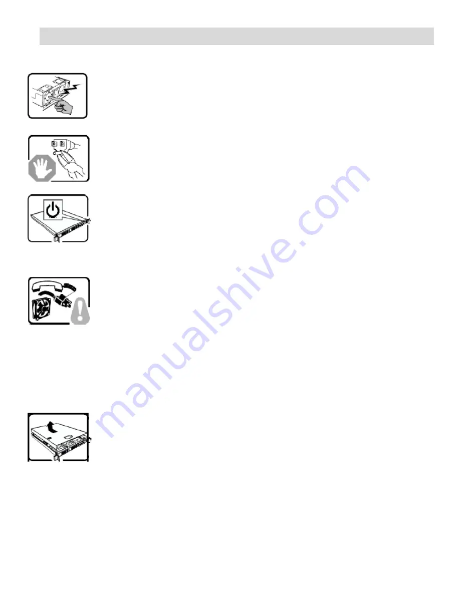
The power supply in this product contains no user-serviceable parts. There may be more
than one supply in this product. Refer servicing only to qualified personnel.
Do not attempt to modify or use the supplied AC power cord if it is not the exact type
required. A product with more than one power supply will have a separate AC power cord
for each supply.
The power button on the system does not turn off system AC power. To remove AC
power from the system, you must unplug each AC power cord from the wall outlet or
power supply.
The power cord(s) is considered the disconnect device to the main (AC) power. The
socket outlet that the system plugs into shall be installed near the equipment and shall
be easily accessible.
SAFETY STEPS
: Whenever you remove the chassis covers to access the inside of the
system, follow these steps:
1.
Turn off all peripheral devices connected to the system.
2.
Turn off the system by pressing the power button.
3.
Unplug all AC power cords from the system or from wall outlets.
4.
Label and disconnect all cables connected to I/O connectors or ports on the back of
the system.
5.
Provide some electrostatic discharge (ESD) protection by wearing an antistatic wrist
strap attached to chassis ground of the system
—
any unpainted metal surface
—
when
handling components.
6.
Do not operate the system with the chassis covers removed.
After you have completed the six SAFETY steps above, you can remove the system
covers. To do this:
1.
Unlock and remove the padlock from the back of the system if a padlock has been
installed.
2.
Remove and save all screws from the covers.
3.
Remove the covers.
Summary of Contents for M10JNP2SB
Page 2: ... Blank page ...
Page 15: ...Intel Server Board M10JNP2SB User Guide 15 Figure 4 Component height restrictions ...
Page 16: ...Intel Server Board M10JNP2SB User Guide 16 Figure 5 Major components and connectors 1 of 2 ...
Page 17: ...Intel Server Board M10JNP2SB User Guide 17 Figure 6 Major components and connectors 2 of 2 ...


