background image

INDEX


USER MANUAL - OPTIMA RT10 1K/1.5K/2K/3K (UL) 


www.xmart-ups.com 

VER.2010.22-One (ENG)


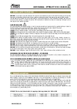
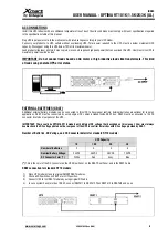
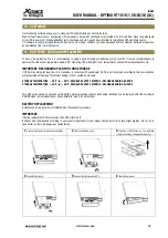
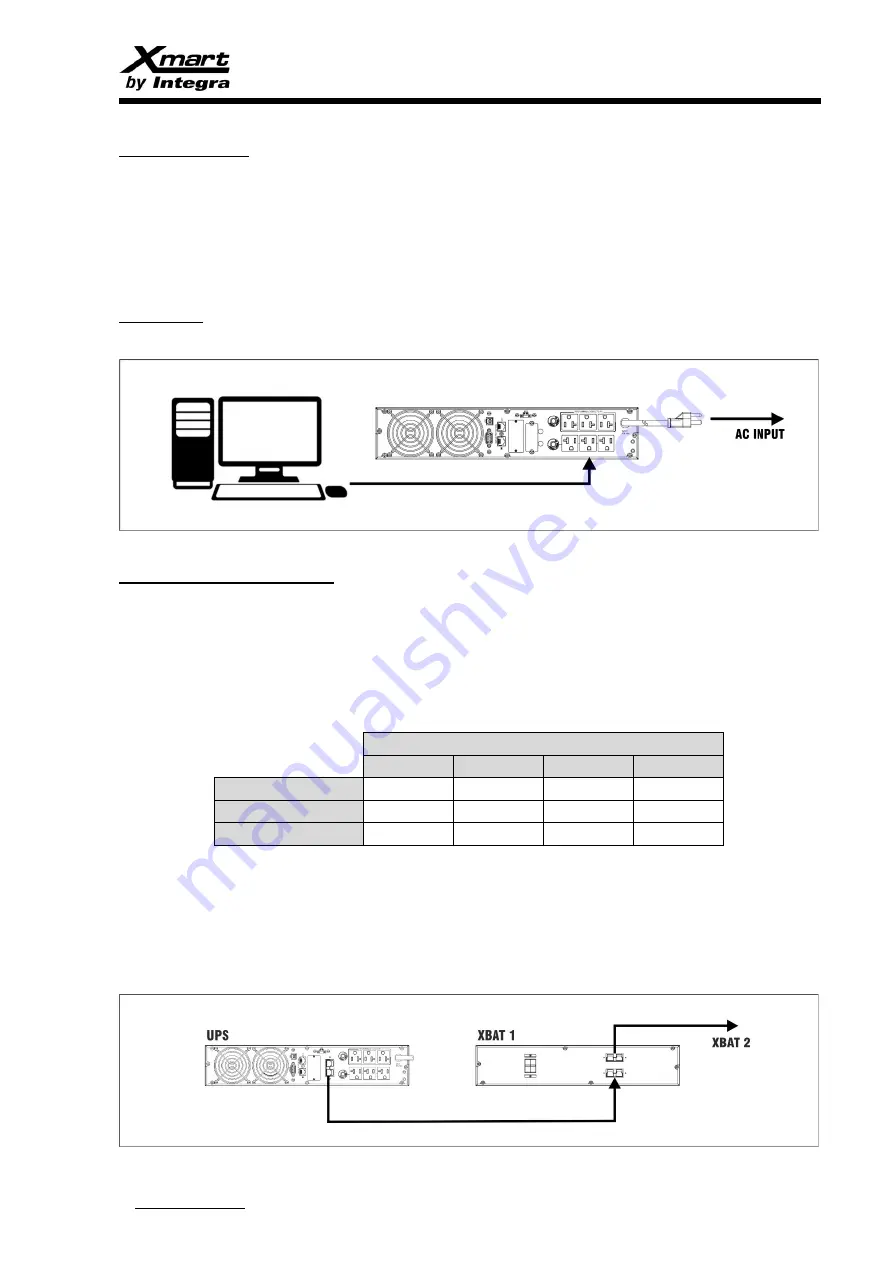
AC CONNECTIONS 

Install this UPS indoors with a conditioned temperature free of dust. The site conditions must comply with room specifications required 

in the specifications table of this manual. 


Plug UPS input power-cord to the wall socket with rated voltage according to your UPS model. 

Connect  your  products  to  UPS  outlets  without  overloading  UPS.  Total  power  required  to  the  UPS  must  be  below  maximum  UPS 

capacity. We suggest using this UPS below 75% of its maximum power. 

Load products like laser printers, Xerox copiers or scanners requires high peak power that can overload this UPS. User must size UPS to 

maximum power required by load. 


IMPORTANT: Do not connect loads based on AC motor or high inductive loads like transformers. This kind 

of loads can generate UPS error states. 


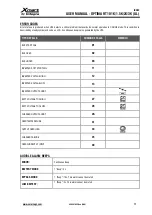
EXTERNAL BATTERIES (XBAT) 

Additional external battery modules can be connected to this UPS to have longer runtime. External batteries are optional for long run 

applications.  XBAT  must  be  connected  by  using  original  DC  cables  included  inside  XBAT  box.  XBAT  must  be  connected  to  the  DC 

connector located on rear panel of the UPS. 


IMPORTANT:  There  could  be  OPTIMA  RT10  models  with  different  DC voltage  that  described  on  this  manual. User  must  always 

double check the DC voltage printed on the rear panel of the UPS to confirm it marches with DC voltage provided by XBAT. 


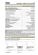
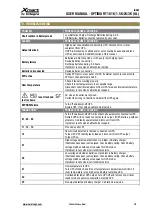
Number of Batteries, DC Voltage, and DC Connector details for standard RT10 models: 


UPS Capacity 


1K 

1.5K 

2K 

3K 

Number of Batteries 

Nominal Battery Voltage: 

24VDC 

36VDC 

48VDC 

72VDC 

DC Connector Color (*) 

White 

Red 

Grey 

Blue 

(*)

 This is the color of the DC connector on the UPS Rear Panel, on the XBAT Rear Panel, and in the XBAT Cable 


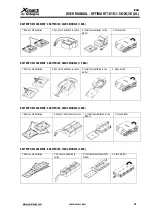
XBAT connection for standard RT10 models:


1)


Place UPS module close to original XMART XBAT modules.  

2)


Check all DC switches on XBAT are in OFF position. 

3)


Connect UPS to first XBAT module by using original DC cable 

4)


In case system has more than 1 XBAT, connect XBAT#1 to XBAT#2. Then XBAT# 2 to XBAT#3 and so on. 


Summary of Contents for Xmart OPTIMA RT10 1.5K

Page 1: ...n on this manual is property of XMART This manual Information cannot be copied or distributed totally or partially without written approval of XMART XMART can introduce modifications in their products...

Page 2: ...STRUCTIONS 2 PRODUCT DESCRIPTION 3 SAFETY QUALITY AND PERFORMANCE STANDARDS 4 INSTALLATION 5 OPERATION MODES 6 OPERATION INTERFACE KEYBOARD LCD 7 UPS CONFIGURATION 8 ERROR ALARMS CODES 9 TROUBLESHOOTI...

Page 3: ...ge the unit permanently WARNING Do not connect AC motor based equipment without a careful sizing of the UPS based on inrush current instead of average current Inrush current typical of motor based sys...

Page 4: ...NG Modifications made on the product or the use of this product as a part of a more complex system not expressly approved by the party responsible for compliance could void the user s authority to ope...

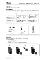
Page 5: ...d only by these handles 1 Install black handles to the UPS 2 Make sure rack cabinet counts with required mounting guides 3 Place UPS on the guides and fix it to the cabinet using black handles VERTICA...

Page 6: ...connected to this UPS to have longer runtime External batteries are optional for long run applications XBAT must be connected by using original DC cables included inside XBAT box XBAT must be connect...

Page 7: ...Bypass mode is adopted in case ON button has not been activated as soon as UPS detects a valid AC input on its terminals If bypass mode is not enabled UPS will simply light its LCD Outputs will keep p...

Page 8: ...ut UPS output is generated by inverter BATTERY MODE A Input indicator at bottom left corner A shows Battery voltage since there is no valid AC input detected B Output indicator displays AC output gene...

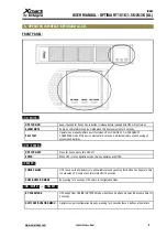
Page 9: ...f test performs a full checking of systems and batteries OFF ENTER UPS TURN OFF Press for 2 seconds to turn UPS off ENTER When UPS is in configuration mode this key operates as ENTER SELECT CHECK VALU...

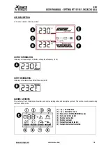
Page 10: ...NPUT INFORMATION It displays AC output voltage Output frequency in Hz ALARMS ERRORS This section of the LCD displays active alarms and errors providing codes and descriptive symbols This section also...

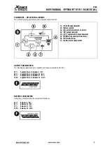
Page 11: ...mable output powered 5 BYAPSS internal static line active 6 ECO mode active 7 Audible alarm beep muted OUTPUT POWER METER This area displays graphically by a 4 segments bar the power supplied by the U...

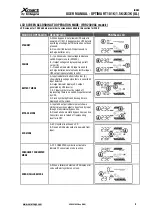
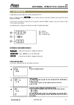
Page 12: ...ODE ON MUTE Used as key to navigate or changing parameters value OFF ENTER Used as ENTER key to confirm modifications SELECT Used as key to navigate or changing parameters value CONFIGURATION MENU For...

Page 13: ...of nominal voltage Factory set 6Vac Set values with keys 06 BYPASS ENABLE DISABLE ENA ENABLE DIS DISABLE Factory set DIS 07 BYPASS INPUT VOLTAGE RANGE Set values with keys Valid input VOLTAGE range fo...

Page 14: ...TTERY CHARGER CURRENT Sets recharging current in Amps 1 2 4 6 or 8 A 14 BOOSTING CHARGING VOLTAGE NO MODIFICATIONS RECOMMENDED ONLY FOR TECHNICIANS Charging voltage can be increased Adjustable Voltage...

Page 15: ...Active Open AC Active Close BAH Battery AH BAT Battery BR Battery Replacement CBV Charger Boost Voltage CFV Charger Float Voltage CF Frequency Converter Function CHA Charger current CH Charger Batter...

Page 16: ...symbols and codes with intermittent beeps Tipo de ALARMA SIMBOLO INTERMITENTE ALARMA SONORA OVERLOAD UPS Load exceeds UPS capacity 1 beep s LOW BATTERY 1 beep 2s BATTERY FAULT 1 beep 2s BATTERY REPLA...

Page 17: ...the UPS TIPO DE FALLA CODIGO DE FALLA SIMBOLO BUS START FAIL 01 BUS OVER 02 BUS UNDER 03 INVERTER SOFT START FAIL 11 INVERTER VOLTAGE HIGH 12 INVERTER VOLTAGE LOW 13 INVERTER OUTPUT SHORT 14 BATT VOLT...

Page 18: ...tion and install the UPS again EEPROM Failure Turn off and power off UPS Restart UPS If not solved call technical service ERROR CODES PROBABLE CAUSE SOLUCION 01 02 03 Turn off and power off UPS Discon...

Page 19: ...f UPS will be stored for long time it is mandatory to recharge UPS periodically If UPS is not recharged according to this plan batteries will get permanent damage This kind of damage is not covered by...

Page 20: ...MENT 3 BATTERIES 36VDC MODELS 1 5KVA 1 Remove old batteries 2 Connect 2 batteries in series 3 Install new batteries in the binder 4 Close binder BATTERY REPLACEMENT 4 BATTERIES 48VDC MODELS 2KVA 1 Rem...

Page 21: ...ry charger uses a 3 steps algorithm to care batteries 1 Constant Current During this stage charger injects a constant current meanwhile batteries increase their voltage During this stage batteries rec...

Page 22: ...ribution service partners reserve the right to charge handling fee if returned product is free of failure or it is out of warranty because any of the reasons described in this warranty 6 If product is...

Page 23: ...C SELECT 6 Emergency power off connector port D OFF ENTER 7 USB RS232 ports 1 Standard UPS outlets 8 Intelligent SNMP port 2 Programmable outlets 9 External Battery connector optional in some models 3...

Page 24: ...INDEX USER MANUAL OPTIMA RT10 1K 1 5K 2K 3K UL www xmart ups com VER 2010 22 One ENG 24...

Page 25: ...5 Electronic inverter shortcircuit protection Protecci n contra cortocircuitos en la salida Triggered by output current over 400 of nominal current during 5 cycles Activaci n a 400 de la corriente no...

Page 26: ...alida es configurable entre 4 alternativas seleccionables en el LCD N2 Backup time for programable outlets can be configurable in minutes Las salidas programables pueden configurarse en minutos N3 All...

Page 27: ......

Page 28: ...USA Headquarters 10540 NW 26th St Doral FL 33172 USA EUROPE Headquarters Ave Can Bordoll 60 Nave 4 Sabadell 08202 Spain Latin America Headquarters Santiago de Chile 8330669 Chile CHILE...

Reviews: