


4.4 Calibration
The
STL6
service tool or
DPT6 EasyConfig
Software are available for convenient on-site calibration.
There is also the possibility to exchange the SC against a calibrated SC on site. The used SC can then be
calibrated directly in the office or at
INTEC Controls
and then reused.
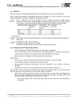
Prior to calibration the Sensor Cartridge must be supplied with power voltage without
interruption for warm-up and stabilisation. The warm-up time depends on the sensor element
and is shown in the following table for Example: See also User Manual for Sensor Cartridge.
Sensor Cartridge
Warm-up for
calibration
(h)
Stabilization time
to specification
(min)
Flow rate
(ml/min)
CO
24
60
150
NO
2
24
60
500
LPG (C
3
H
4
)
24
60
150
Table Calibration
Please observe proper handling procedures for compressed gas and test gas bottles (regulations
TRGS 220)!
Test gas can be toxic, so never inhale it!
Symptoms: Dizziness, headache and nausea.
Procedure if exposed: Remove victim to fresh air, seek medical attention.
4.5 Calibration with
DPT6
EasyConfig
Software
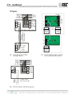
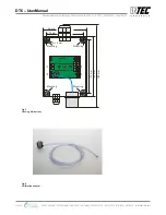
•
Connect
DPT6 EasyConfig Software
Interface to the
DT6
Basic Sensor Board.
Prior to calibration you have to activate the mode “Special Mode” at the BSB, only then the
calibration menu is enabled. During the special mode the BSB doesn’t issue alerts.
•
Select the Sensor Cartridge to be calibrated by selecting the gas type.
Zero calibration
•
The current zero offset and the offset value of the first calibration is read with "Read".
•
Slide calibration adapter carefully onto the Sensor Cartridge.
•
Apply synthetic air (flow rate according to the table "calibration", 1 bar ± 10%) to the Sensor
Cartridge.
•
When the value is stable, the new zero offset factor is calculated with "Calibration".
The new offset factor is checked for plausibility and stored in the buffer memory. The current measured
value is output with the new offset factor and the offset display is updated.
•
With "Save" the new offset factor is written in the SC memory, only then the Zero calibration has
been successfully completed. If you exit the menu without pressing "Save", the original offset data
for the measured value calculation will continue to be used.
With a zero reading> 10% of measuring range during the zero calibration, zero calibration is
not possible.
INTEC Controls | 12700 Stowe Drive, Suite 100, Poway, CA 92064 | Ph: (858) 578.7887 & (888) GO.INTEC | inteccontrols.com
Specifications subject to change without notice. | GASB2_03_E_0220 | USA 200306 | Page 7 of 15
DT6 – UserManual


