


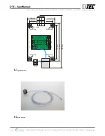


4.1 Installation of Sensor Cartridge
The Sensor Cartridge is supplied in a separate package and should be installed on the housing only during
commissioning to protect it against dirt and damage.
•
Check gas type, range and calibration date of Sensor Cartridge.
•
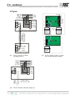
Define installation place on the housing of the basic or remote sensor and break out knockouts. See
Fig. 3
•
Insert Sensor Cartridge, O-ring seal must rest on the housing exterior.
•
Tighten the Sensor Cartridge with M32 hexagon lock nut.
•
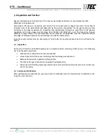
Plug in the Sensor Cartridge at X2 or X3 of the sensor board. Observe plug polarity, the plug must
engage.
4.2 Addressing
A basic communication address is assigned to the
DT6 board
with the help of the
STL6
Service Tool or the
DPT6
EasyConfig
Software. Using this basic address, the data of the Sensor Cartridge assigned to input 1 are
sent via the field bus to the gas controller. Any further SC connected / registered on the
printed circuit board
automatically gets the next address.
4.3 Registration / Assignment of the Sensor Cartridge(s) (SC)
The
DT6
recognizes automatically the SC(s) physically connected to
it
(unimportant whether directly on the
DT6
or on the
remote DR6
) via the gas type and the measuring range which are factory-integrated in the SC
address bit. By selecting the signal type, analog or bus, the input is activated. In the second step by assigning
the gas type and defining the measurement range, the SC is connected to the input.
Up to
two
different SC can be connected at the
DT6, with a third to an attached remote DR6
. The physical
position of the SC does not have to agree with the input in the menu.
Example:
DT6
with three SCs for CO, NO
2
and C
3
H
4
with basic address 09
Input Mode Field Bus
Address
Gas
Type
Measuring
Range
Result
1
SC
DP 09
CO
300 ppm
CO SC assigned to input 1 und thus field bus address DP09
2
SC
DP 10
NO
2
30 ppm
NO
2
SC assigned to input 2 und thus field bus address DP10
3
SC
DP 11
C
3
H
4
100 % UEG C
3
H
4
SC assigned to input 3 und thus field bus address DP11
Only the parameters with blue background have to be worked on for the BSB addressing and the SC registration.
Mode:
Not active: = SC assignment to input not possible
SC:
= SC assignment possible
Analog:
= Input with 4-20 mA signal, assignment possible
Gas type and meas. range:
Selection of gas type and measuring range of the SC connected to the
input or of the analog sensor
The registration is only accepted if the assigned gas type/measuring range are identic in the BSB and in the
SC. Gas type and measuring range of the BSB are checked for identity by the GC Controller, too.
Only one SC per gas type must be connected to the same
DT6
Basic Sensor Board.
Two SC2 sensor heads of the same gas group (Freons) must not be connected.
INTEC Controls | 12700 Stowe Drive, Suite 100, Poway, CA 92064 | Ph: (858) 578.7887 & (888) GO.INTEC | inteccontrols.com
Specifications subject to change without notice. | GASB2_03_E_0220 | USA 200306 | Page 6 of 15
DT6 – UserManual


