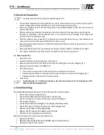
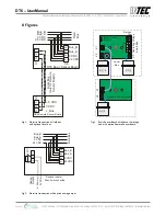
Intec PolyGard 2 DT6 User Manual Download Page 13


Fig. 3 

Mounting possibilities 
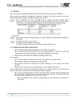
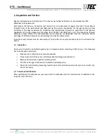
Fig. 4 

Housing knockouts 

X2

X2

X2

X3

X3

X4

4
3
2
1

X4

4
3
2
1

X7

3

2

1

X7

3

2

1

X7

3

2

1

Basic Sensor Board

Basic Sensor Board

Remote Sensor Board

B

as

ic

 S

ens

or


B

as

ic

 S

ens

or


R

em

ot

Se

ns

or


Lo

ca

l

Bus

Field Bus

Bas

ic 

Sen

so

r Bo

ard

wi

th

t t

wo

Sen

so

r C

art

ridg

e

Ba

sic

 S

en

so

r Bo

ard

wi

th

 tw

Se

nso

r S

C &

Re

m

ot

e Sen

so

r B

oar

wi

th 

Sen

sor

 C

ar

tri

dge

Field Bus

M25

M12

M25

M25

M25

M25

M20

M20

M12

SC

SC

SC

SC

SC

Bas

ic

 Se

ns

or

 Bo

ar

wi

th

 Sen

sor

 C

ar

tri

dge

Bas

ic

 Se

ns

or

 Bo

ar

d

wi

th

 SC

 & 

Re

m

ot

Sen

sor

 B

oar

w

ith 

SC

Bas

ic

 Se

ns

or

 w

ith 

SC

 &

 tw

o R

em

ot

Sen

sor

 B

oar

w

ith 

SC

X2

X2

X2

X2

X2

X2

X3

X3

X3

SB_03

SB_03

SB_03

SB_03

SB_03

SB_03

X4

4
3
2
1

X4

4
3

2
1

X4

4
3
2
1

X7

3

2

1

X7

3

2

1

X7

3

2

1

X7

3

2

1

X7

3

2

1

X7

3

2

1

Basic

Sensor Board

Basic 

Sensor Board

Basic

Sensor Board

Remote 

Sensor Board

Remote 

Sensor Board

Remote 

Sensor Board

Ba

sic

 Se

ns

or


Loc

al

Bus

Loc

al

Bus

Loc

al

Bus

Rem

ot

Sen

so

Rem

ot

Sen

so

R

em

ot

e S

en

sor


Field Bus

Field Bus

Field Bus

M25

M25

M25

M12

M12

M12

M12

M12

M12

M25

M25

M25

M20

M20

M20

Ba

sic

 Se

ns

or


Ba

sic

 Se

ns

or


SC

SC

SC

SC

SC

SC

M20

M20

M25

M20

M12/M20

M12/M20

M25

M25

M20

M1

2

M1

2

INTEC Controls | 12700 Stowe Drive, Suite 100, Poway, CA 92064 | Ph: (858) 578.7887 & (888) GO.INTEC | inteccontrols.com

Specifications subject to change without notice. | GASB2_03_E_0220 | USA 200306 | Page 13 of 15

DT6 – UserManual

Summary of Contents for PolyGard 2 DT6

Page 1: ...Transmitters Serial No SB 03 User Manual Version February 2020 en ref optional remote sensor DR6 INTEC Controls 12700 Stowe Drive Suite 100 Poway CA 92064 Ph 858 578 7887 888 GO INTEC inteccontrols c...

Page 2: ...5 Inspection and Service 9 5 1 Inspection 9 5 2 Service and Calibration 9 6 Troubleshooting 10 6 1 DT6 Basic Sensor Board 10 6 2 SC2 Sensor Cartridge Messages at the Tool Controller 10 7 Technical Dat...

Page 3: ...local bus level is done via the STL6 Service Tool or with the DPT6 EasyConfig Software which is directly connected to the BSB The cable topology for the RS 485 field bus can be taken from the Guideli...

Page 4: ...eight depends on the relative density of the gas type to be monitored Choose mounting location of the sensor according to the local regulations Consider ventilation conditions Do not mount the sensor...

Page 5: ...SB connect cable according to connection diagram fig 1 Replug terminal carefully on the BSB at X4 For remote sensor Insert and connect local bus cable at the basic and remote sensor board Remove termi...

Page 6: ...as type and defining the measurement range the SC is connected to the input Up to two different SC can be connected at the DT6 with a third to an attached remote DR6 The physical position of the SC do...

Page 7: ...on you have to activate the mode Special Mode at the BSB only then the calibration menu is enabled During the special mode the BSB doesn t issue alerts Select the Sensor Cartridge to be calibrated by...

Page 8: ...g the SC connector which leads to an immediate triggering of the error message Disconnect the SC connector from the BSB or the RSB error message will be activated Loosen the locknut Remove used SC Tak...

Page 9: ...be documented The date for the next maintenance has to be affixed to the sensor 5 1 Inspection Gas sensors should be controlled regularly by a competent person according to EN 45544 4 The following ha...

Page 10: ...h with registered ones Check SC data registration data for conformity Message at the Tool Controller 24 V DC voltage range 5 V DC voltage range Temp range WatchDog triggered Internal error Replace BSB...

Page 11: ...B x D 94 x 130 x 57 mm 3 7 x 5 1 x 2 2 in Weight 0 3 kg 0 7 lb Protection class delivery status NEMA 4X IP 65 Installation Wall mounting Wire connection Field bus Local bus for SC Screw type terminal...

Page 12: ...oard Local Bus only for Remote Sensor Board Field Bus 1 2 3 4 0 VDC 24 VDC Bus_A Bus_B Bus_B Bus_A 24 VDC 0 VDC Analog Output 4 20 mA 0 VDC Field Bus 1 2 3 500 Remove resistor if device is connected X...

Page 13: ...rd with SC X 2 X 2 X 2 X 2 X 2 X2 X 3 X 3 X 3 SB_03 SB_03 SB_03 SB_03 SB_03 SB_03 X4 4 3 2 1 X4 4 3 2 1 X4 4 3 2 1 X7 3 2 1 X7 3 2 1 X7 3 2 1 X7 3 2 1 X7 3 2 1 X7 3 2 1 Basic Sensor Board Basic Sensor...

Page 14: ...Mounting Mounting Mounting Mounting 115 mm 130 mm 180 mm D 4 mm INTEC Controls 12700 Stowe Drive Suite 100 Poway CA 92064 Ph 858 578 7887 888 GO INTEC inteccontrols com Specifications subject to chan...

Page 15: ...de ANSI NFPA70 The equipotential bonding required also e g secondary potential to earth or grounding measures must be carried out in accordance with the respective project requirements It is important...

Reviews: