


Intended Use
The PolyGard
2
DT6
are designed for the detection of toxic, combustible or dangerous atmosphere in many
commercial and industrial applications in connection with the Gas Controller System DGC6.
The intended sites are all areas being directly connected to the public low voltage supply, e.g. residential,
commercial and industrial environments as well as small enterprises (according to EN 50 082).
The PolyGard
2
Series
must not be used in potentially explosive atmospheres. The sensor must only be
employed in areas within the environmental conditions specified in the Technical Data.
1 Functional Description
1.1
General
The Sensor consists of the two components
DT6
Basic Sensor Board (BSB) and
SC2
Sensor Cartridge (SC).
The Sensor Cartridge contains a µController for signal processing besides the sensor element and the
measuring amplifier. All data and measured values of the sensor element are stored fail-safe in the
µController and transferred digitally via the local bus to the
DT6
Basic Sensor Board. The calibration
management is also integrated in the µController of the
SC2
Sensor Cartridge.
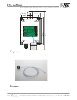
The
DT6
Basic Sensor Board has got three local bus interfaces for connection of up to three Sensor Cartridges
and a field bus interface (RS-485) for communication with the
DGC
6 Gas Controller. The
DT6
Basic Sensor
Board is integrated in the system as a slave with its basic address. The addressing on the field bus level as
well as the registration and assignment of the Sensor Cartridge on the local bus level is done via the
STL6
Service Tool or with the
DPT6 EasyConfig Software
, which is directly connected to the BSB.
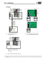
The cable topology for the RS-485 field bus can be taken from the “Guidelines for wiring and commissioning
of the DGC6 hardware”.
1.2
Measuring Mode
The sensor element continuously monitors the ambient air to detect an existing gas concentration and
transmits a measurement signal which is proportional to the gas concentration via the amplifier directly to
the AD converter of the µController. The µController checks the measurement signal for plausibility (within
defined measuring, temperature and voltage ranges, etc.), calculates the average and sends both values with
the attributes gas type and unit via the local bus to the µController of the
DT6
Basic Sensor Board. The BSB
(slave) sends the data of the registered Sensor Cartridge upon polling request to the
DGC
6 Controller
(master).
1.3
Special Mode
If a fault occurs (measurement signal, temperature or operating voltage outside the defined range,
communication error on local bus) or when the
DT6
Basic Sensor Board is in the maintenance/calibration
mode, the measurement operation is interrupted and the status of "special mode" is sent to the
DGC
6
Controller.
The integrated measuring amplifier converts this change in resistance into a linear output signal. The
continuous combustion leads by-and-by to a loss of sensitivity that can be compensated by performing
regular calibration of zero and gain. See section 4.4.
INTEC Controls | 12700 Stowe Drive, Suite 100, Poway, CA 92064 | Ph: (858) 578.7887 & (888) GO.INTEC | inteccontrols.com
Specifications subject to change without notice. | GASB2_03_E_0220 | USA 200306 | Page 3 of 15
DT6 – UserManual


