


X.
AUXILIARY MODE
AUXILIARY TRIM PROGRAMMING:
The
Auxiliary
input is used in the Follower mode to change the relationship between
the Master and Follower motor speeds, based on the input of a third frequency. This
frequency is commonly generated with Drive Control System’s AIFO-200 (analog-to-
frequency converter). The input to the AIFO-200 can be generated by a dancer pot, a
pressure transducer, or any other device with a 0-10V or 4-20mA output.
In Auxiliary Trim mode, the
Auxiliary Frequency
input trims the final Follower motor
speed by adding or subtracting Auxiliary pulses to the Lead frequency, making the
Follower motor increase or decrease speed. The speed change is determined by the
following formula:
(Var 25) (Var 26)
Aux Freq Input Hz
-
1/2 Aux Ref Freq
(Var 01)
x Aux Gain x
Max Feedback
1/2 Aux Ref Freq
(Var 25)
Multiply the Result by -1 if Var 27 is 0
The Auxiliary error count from this formula is summed in every .02 seconds as long as
the lead motor is running. When the lead motor stops, the error count is returned to zero.
There are provisions for adding a delay on start-up, adjusting the amount of authority or
gain of the Auxiliary input, polarity change (increasing frequency decreases speed or
increasing frequency increases speed), and the frequency input programming.
Variable 24- Auxiliary Mode Selection
- 0000 -Auxiliary Input is disabled. 000l-
Auxiliary Trim mode is active.
Variable 25- Auxiliary Reference Frequency
-
Enter the maximum frequency of
the auxiliary input. Zero trim correction is 50% of the programmed frequency; 9,999 Hz
maximum.
Variable 26- Auxiliary Gain Percentage -
This value is the percentage of maximum
speed (Variable 01) that can be corrected by the Auxiliary Trim mode. Enter 0 to 999%.
Variable 27- Auxiliary Trim Selection
-
Entering 0000: Increasing the frequency
above 50% of the auxiliary reference frequency will decrease motor speed. Decreasing
the frequency will increase motor speed. Entering 0001
:
Increasing the frequency above
50% of the auxiliary reference frequency will increase motor speed. Decreasing the
frequency will decrease motor speed.
Variable 28 - Auxiliary Input Delay
-
Delays the start of the Auxiliary Trim
function on startup. Enter the number of 10 msec update cycles to wait. When
ENTER
is pressed, the MicroSpeed 196 will insert a decimal point to display the delay in
seconds.
21
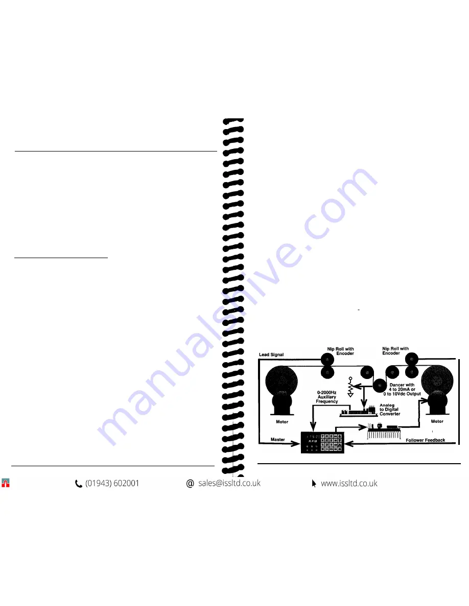
EXAMPLE:
In this application, (see Diagram 7, below) the MicroSpeed 196 is programmed to
control the wind-up (Follower) motor in a one-to-one relationship with the unwind
(Master) motor. Tension is controlled by a dancer arm. We will use 1000 rpm on the
encoders as the maximum speed of both the unwind (Master) and wind up (Follower)
reels. This would be entered into Variable 04
(Maximum Lead RPM)
and Variable 01
(Maximum RPM).
We will assume a 12-inch circumference on the nip rolls. Because
of this, we can enter 1000 into Variable 02
(User Units at Max RPM)
and the tach
will display ft/min. The PPR of the encoders is entered into Variable 03
(Feedback
PPR)
and Variable 05
(Lead PPR).
Enter the Ratio Set Point 1.000. The MicroSpeed
196 is now programmed to run in a one-to-one Master/Slave relationship. The machines
should now be operated, and PID tuning is completed.
The AIFO-200 has been programmed to provide a 0 - 2000 Hz output, based on a 0 -
10V input signal from the dancer. 2000 is entered into Variable 25
(Auxiliary
Reference Frequency).
The MicroSpeed 196 will add correction whenever the
Auxiliary Reference frequency
is not l/2 value. Set Variable 26
(Auxiliary Gain
Percentage)
at 10% to start with, and change Variable 24
(Auxiliary Mode
Selection)
to 1, to enable the input as a trim function. Variable 27
(Auxiliary Trim
Selection)
will be set to 0. This gives a decrease in Follower motor speed, with an
increase in input frequency from the AIFO.
After starting the machine with the
Auxiliary
input active, (Variable 26)
Auxiliary
Gain Percentage
can be adjusted. Higher percentages result in tighter control;
however percentages that are too high will cause instability. It may also be desirable to
delay the Auxiliary trim on a start command. This allows the motors to get up to speed,
or above the low torque range, before adding extra correction changes. Use Variable 28
(Auxiliary Delay)
for this function.
Diagram 7
Typical Auxiliary Trim Mode Application:
AIFO -
200
AC or DC Drive
MicroSpeed 196
22
Summary of Contents for MicroSpeed 196
Page 1: ...MSMAN32C MicroSpeed 196...
Page 19: ......


