


2234-223 Rev. 10/9/2019 3:36 PM / See Owner’s Manual for Warranty Information.
Protected under U.S. and foreign patents (see
www.insteon.com
)
© Copyright 2019 Insteon, 1621 Alton Parkway, Suite 100, Irvine, CA 92606, 800-762-7845
Quick Start Guide
Insteon® Serial Interface Modem
(Dual-Band)
Model: 2234-223
Insteon Modem Features
Expanded operation to 100-240VAC and 50/60Hz.
Increased Insteon links storage from ~1000 to ~4,000 links with faster read/writes
Uses the same communication protocol and structure to match earlier models
Updated all processors with increased memory space and speed
Beefed up electronics to reduce failures due to AC-mains electrical spikes,
noise and heat from poorly ventilated install locations
New and smaller enclosure that matches other Insteon plug-in products
Increased powerline transmitting signaling levels and robustness
New RF circuit with higher sensitivity components and calibrated antenna circuit
Supplies 5VDC capable of powering single-board computers like ISY™ controllers
Added fast TVS surge suppression on the Serial port to prevent static damage
Install Insteon Modem
1) Ensure Insteon Modem is
not
plugged into your computer
2) Plug clear end of included DB-9 serial cable into Modem’s RS-232 interface port
3) Plug black end of cable into an available serial port on your PC
4) Plug Insteon Modem into an AC wall outlet
Insteon Modem is now ready
Connector
Specifications Communications
Pin 1: RS232 to PC pin 2 (Rx)
Pin 2: +5VDC (1A)
Pins 3 - 6: Not connected
Pin 7: Common ground
Pin 8: RS232 from PC pin 3 (Tx)
Tips for Using Insteon Modem
Never plug Insteon Modem into a power strip or AC line filter
Use only one Insteon Modem per computer
Do not place near large metal objects, such as refrigerators or TVs
Some computers and their accessories can absorb Powerline Carrier (PLC) signals off the powerlines. Since Insteon Modem
will be close to the computer, the power strip for the computer should be filtered. Use an Insteon FilterLinc (#1626-10) on the
computer’s power strip to keep Insteon Modem signals from getting absorbed by the computer equipment
If computer’s serial port is shared with another hardware device (scanner, PDA, etc.) be sure to turn off that device’s program
on the PC. If left running, the home automation software will not be able to communicate with Insteon Modem.
To reset to its original settings, unplug the modem from the wall outlet & wait 10 seconds. Press & hold the Set button; while
continuing to press and hold, plug back in. A long beep will sound; continue holding Set button until beep stops, then release.
After several seconds, status LED will turn on to indicate reset is complete
Use Insteon Modem as a Phase Bridge
1)
Install additional dual-band Insteon devices if they are not already installed
2)
Start Phase Detection Mode by tapping the Set button on Insteon Modem four times quickly
Insteon Modem will begin beeping and status LED will turn on solid green
3)
Check the LED behavior of the other dual-band devices to see if they are on the opposite phase
If at least one of the dual-band device LEDs is blinking green or is bright solid white or blue, the device is on the opposite
phase. Continue on to step 4.
If none of the dual-band devices exhibit the behavior above, they are on the same electrical phase. Try the following:
Follow steps 2 and 3 with the other dual-band devices to see if they are exhibiting the desired LED behavior
Move a dual-band device to another location until it exhibits the desired LED behavior
4)
Tap Insteon Modem Set button
Insteon Modem will stop beeping
Owner’s Manual and Tech Support
Owner’s Manual and current Quick Start Guide:
http://www.insteon.com/support
Call: Insteon Support Line at 800-762-7845
The RS 232 serial communications to Modem are:
19,200 baud
8 data bits
No parity
1 stop bit
NOTE: each byte sent to Insteon Modem will be
echoed back to the host.
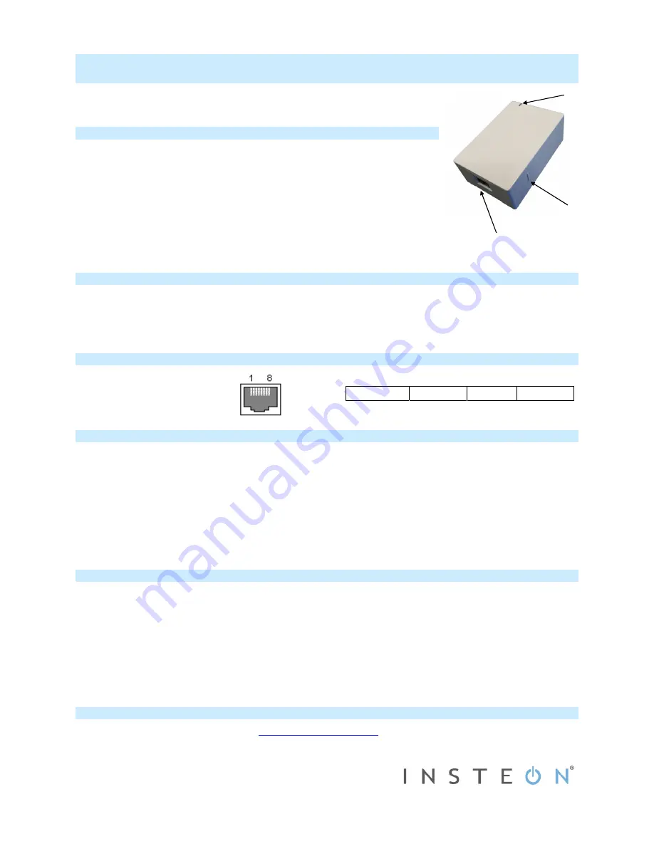
Set
Button
LED
Indicator
RS-232
Interface


