background image

70

Chapter Ten Server Installation Guide

Chapter Ten Server Installation Guide

with requirements of the server.

10.2 Components Needed in Server Installation

10.2 Components Needed in Server Installation

Accompanying guide rail suit of 2U server includes the following objects:
1. Guide rail              

1 set (one for left and one for right rail)

2. Fixing screw          

1 wrap 

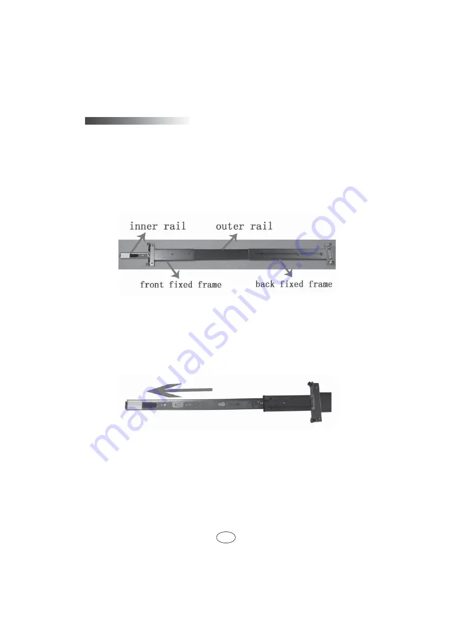
The rail consists of inner rail, outer rail and 

fi

 xed frame, just as shown in (picture 1).


Picture 1

10.3 Installation of Inner Rail

10.3 Installation of Inner Rail

Please install the inner rail to the cabinet according to the following description.
1. Firstly, take out the inner rail from the guide rail: hold the front 

fi

 xed frame of 

the whole guide rail and pull outward the inner rail, just as shown in (picture 2).

 Picture 2

2. When the inner rail can’t be pulled any more, stir the bayonet lock shown in 

(picture 3) along the direction of arrow, and then pull outward the inner rail completely 
with even strength.


Summary of Contents for NF5220

Page 1: ...humankind s benefit This manual is the property of the Inspur Group Co Ltd This User Manual is not to be copied by any group or person in any manner without the consent of Inspur Group Co Ltd The Inspur Group Co Ltd reserves the right of revising this manual momentarily Any alteration about the content of this manual will not be noticed Please contact Inspur Group Co Ltd if you have any questions ...

Page 2: ...dard Please don t use them with the corresponding components of any other computers con fusedly 4 When you have any software problems during the application of this server we hope that you firstly contact the corresponding software supplier and then he will contact us in favor of communication so as to solve your problem together especially the software problems about the database the installation...

Page 3: ...del is in troduced Chapter Six SATA HostRAID Setup Chapter Six SATA HostRAID Setup In this chapter the setup of onboard SATA HostRAID controller is introduced Chapter Seven Operating System Installation Chapter Seven Operating System Installation In this chapter how to install the main operating system to this server is intro duced Chapter Eight Common Problem and Trouble shooting Chapter Eight Co...

Page 4: ...Model Setup 19 4 1 How to Enter SAS RAID Setting Interface 19 4 2 SAS RAID Menu Description 19 4 3 How to Configure SAS RAID 21 4 4 Rebuild Setting Process 25 Chapter Five SAS RAID of IR Model Setup Chapter Five SAS RAID of IR Model Setup 27 5 1 How to Enter SAS BIOS 27 5 2 The Application of Control Keys 27 5 3 SAS BIOS Setting 27 Chapter Six SATA HostRAID Setup Chapter Six SATA HostRAID Setup 32...

Page 5: ...m 59 8 4 Additional Notes 60 8 5 Technical Support Information 61 Chapter Nine Application Introduction on Baseboard Management Controller Chapter Nine Application Introduction on Baseboard Management Controller 62 9 1 Management Chip BMC IP 62 9 2 Remote Login 62 9 3 Function Menu Introduction 63 Chapter Ten Server Installation Guide Chapter Ten Server Installation Guide 69 10 1 Cabinet Preparati...

Page 6: ...nded cables to matched with correct earthed plug and check the ratings of the extended cables to make sure that the sum of rated current of all products inserted into the extended cables make sure that the sum of rated current of all products inserted into the extended cables do not exceed 80 of the limits of the rated currents of the extended cables do not exceed 80 of the limits of the rated cur...

Page 7: ... bought is the chassis besides carefully read the installation descrip tion attached with the cabinet products and get known about the special warning no tices and installation process you must abide by the following preventive measures to guarantee the cabinet to be stable and safe Warning 10 Before installing equipment in the chassis please install front and Warning 10 Before installing equipmen...

Page 8: ...d make sure that the system is fully dried Close the cover of the host re connect the system to the power socket and then start the equipment In case of operation failure or abnormal situation please contact Inspur and get technical support 3 Pay attention to the position of the system cables and power cables wire them in places not to be stepped on or knocked down and ensure not to place other ob...

Page 9: ...r face on the cabinet regularly to conduct off the static electricity on the body that may damage the internal components 7 When dismounting the internal components with the approval of Inspur please pay attention to the following matters Switch off the system power supply and disconnect the cables including discon necting any connection of the system When disconnecting the cables please grab the ...

Page 10: ...est component When pulling out the components from the cabinet it shall apply force slightly to ensure the cabinet to keep balance and stabilization When pressing down the release latch of the sliding rail of components and slid ing in or out please be careful as the sliding rail may hurt your figures Never make the AC power branch circuit in the cabinet overload The sum of cabinet load shall not ...

Page 11: ...4G I O Interface I O Interface Keyboard and mouse Interface One PS 2 Keyboard interface and one PS 2 mouse interface USB Interface Four rear USB interfaces and one front USB interface Serial Interface One rear serial interface Network Interface Two RJ45 network interfaces Display interface One VAG interface Display controller Display controller Controller type Onboard AST2050 display controller Vi...

Page 12: ...pe 2 5 inches SAS and SATA hard disk Storage Support up to 24 hard disks External memory driver External memory driver CD ROM Slim SATA DVD CD ROM the server with 17 24 hard disks cannot collocate Slim CD ROM Driver U disk Optional to driver U disk Power Power Specification Optional to single or 1 1 redundancy supply Power input Please refer to the power input label near the power interface Physic...

Page 13: ...ation 1 Front USB interface To connect the USB devices 2 Hard disk bay To install the 1st 8th hard disk 3 Hard disk bay To install the 9th 16th hard disk 4 Hard disk bay To install the 17th 24th hard disk 5 CD ROM slot Optional to install the Slim CD ROM Not available when 17 24 hard disks are configured 6 Front control panel To manage the server and display indicator lights Please refer to Front ...

Page 14: ...rk card 1 indica tor light Green flashing network is being connected and data are being transmitted Light off network is disconnected 6 ID light Machine locating light blue 7 Fan failure indicator light It warns fan failure This light is always off when the system is in normal status The light is always amber in case of system fan failure The light is also amber when server is turned off AC power ...

Page 15: ...ication 1 Power input interface For connecting power line the above picture ex ample is for double power supply 2 PS 2 mouse interface For connecting PS 2 mouse 3 PS 2 keyboard interface For connecting PS 2 keyboard 4 Rear USB interface1 2 For connecting USB interface devices 5 Serial interface For connecting serial interface devices 6 VGA interface For connecting display devices 7 Rear USB interf...

Page 16: ...lease record the corresponding origi nal setup Hence when there are operating problems in the system due to the alteration the setup can be reversed 2 The factory default system value is usually the optimized setup Do not try to alter the parameters before you understand their denotations 3 The common setup is introduced in detail in this chapter For items less used in the application this chapter...

Page 17: ... tion on system s automatic detection and configuration A right pointing signal may be found before some item which means this item is selected and press Enter the sys tem will enter the cascading menus i e submenus Operation key introduction Operation key introduction Key Description Up arrow for selecting the upper menu or value Down arrow for selecting the next menu or value Left arrow for sele...

Page 18: ... of week month date year II Advanced menu II Advanced menu The menu is mainly used to set to enhance characteristics Improper setting may cause the abnormal system operation so please keep factory default settings CPU Configuration Display the detailed information installed in the system including manufacturer CPU frequency front end bus the size of cache and so on IDE Configuration The options in...

Page 19: ...figuration This menu can be used to set the system boot process Quick Boot This item is to set the enable quick start system If the system is set to Enabled then it allows BIOS to reduce the boot time by skipping some tests Quiet Boot This item can be used to set the display status during the system boot process Set to Disabled it will show the self test process and test information set to Enabled...

Page 20: ...power state after system s abnormal power off Its default setting is Power Off the state of off which necessitates manual boot for avail ability Power On is the state of on Last State is the state before power off VI Exit Menu The options in Exit menu can be used to save or discard the settings of the chang es in the BIOS and exit the setting program Save Changes and Exit Select this item and pres...

Page 21: ...horting out two pins of the jumper to change the interface functions Refer to the following picture and adjust the motherboard functions Jumper Setting View 3 2 1 Open the Chassis Upper Panel 3 2 1 Open the Chassis Upper Panel If the user need alter motherboard jumpers please first obtain the authorization of Inspur Group Co Ltd Then open the chassis upper panel according to the following steps 1 ...

Page 22: ...n description Jumper function JP1 clearing CMOS jumper Normal state short cut pin 1 and 2 Clearing CMOS short cut pin 2 and 3 JP7 Enabling disabling onboard SAS controller jumper Enabling onboard SAS controller short cut pin 1 and 2 Disabling onboard SAS controller short cut pin 2 and 3 JP11 onboard SAS controller model set jumper IR model short cut pin 1 and 2 SWR model short cut pin 2 and 3 ...

Page 23: ...er supply Af ter short cutting pin2 and 3 it needs to keep for 5 seconds then reuse the jumper cap to short cut pin 1 and 2 default settings of the JP1 to restore the original state 2 Some configuration of this kind of servers motherboard do not integrate SAS controller so they don t have JP7 jumper and JP11 jumper functions ...

Page 24: ...ou purchased does not integrate SAS controller you can skip this chapter 4 1 How to Enter SAS RAID Setting Interface 4 1 How to Enter SAS RAID Setting Interface 1 The screen will display the following English prompt during the booting pro cess of the system Press Ctrl M or Enter to run LSI Software RAID Setup Utility at the same time press Ctrl M keys or Enter to enter RAID setting interface 4 2 S...

Page 25: ...k array and use this option to eliminate all the configuration information on the disk View Add configuration It is used to browse the current disk array configuration information of the system and new disk array configuration can also be added to the current configuration this function can not cause any damage to the current configuration information Clear Configuration Eliminate array configurat...

Page 26: ...AID1 5 4 3 How to Configure SAS RAID 4 3 How to Configure SAS RAID The following is the explanation of how to configure RAID by a specific example Taking the configuration of RAID1 as an example there are two disks for system con figuration and different disks display different information and the information on the following picture only serves as an explanation example for reference 1 After ente...

Page 27: ...er Four SAS RAID of SWR Model Setup 2 Enter the ARRAY SELECTION MENU interface as is shown in the picture below Use Space to select the disk to make RAID array then select 0 Ready and 1 Ready to enter the interface as is shown below and then press F10 ...

Page 28: ...Setup 3 Configuration progress enters the interface as shown below 4 Press Space and the configuration enters the interface as shown below 5 Press F10 and the configuration program displays RAID information to pro vide a window for users to configure RAID parameters as shown below ...

Page 29: ...ter the interface as shown in the second picture of Step 2 8 Press Enter and go into the interface as shown below 9 Select Yes and press Enter and then the RAID1 configuration is completed Press any key to continue go back to Configuration Menu interface 10 Initialize the pre configured RAID Select initialize option from the Management Menu of the configuration main interface and press Enter use t...

Page 30: ...r Enter according to the system prompts to enter SAS RAID con figuration At this point the system will automatically complete the Rebuilding process After the Rebuilding automatic configuration process is completed press ESC key to exit setting according to the system prompts If you do not want to start Rebuild operation at this time press ESC key dur ing the automatic Rebuilding process of the sy...

Page 31: ...D to be rebuilt then press F10 and then press Y according to the prompts to start Rebuilding 3 Wait for the completion of Rebuilding The length of time depends on the size of the disk Please be patient 4 When the Rebuild configuration is finished please exit the configuration pro gram according to the system prompt ...

Page 32: ... Corp Configuration Utility 2 At this point press Ctrl C keys to enter SAS controller setting interface 5 2 The Application of Control Keys 5 2 The Application of Control Keys Key Description For moving cursor in different menus For changing the content of the item value Enter For selecting submenu and displaying all the items in the selected menu Esc For existing menu or going back to the superio...

Page 33: ...erties option press Enter and the system displays Create IM Volume Create IME Volume Create IS Volume Create IM Volume Select this option to allow two hard disks to make RAID1 ar ray RAID1 array can save the data on the main disk transplant the data on the main disk to the auxiliary disk or create a brand new array Create IME Volume Select this option to allow 3 10 hard drives to make RAID1E array...

Page 34: ... if you want to save data on this hard disk and transplant the data on the hard disks to the array If you want to create a brand new RAID1 array please press D and all the data on the hard disk will be eliminated Please select according to your actual needs and here we choose D to establish a brand new RAID1 array With the same method select another hard disk to make RAID1 array After the hard dis...

Page 35: ...he system can make hot backup addition re synchronization of array array ac tivation and array deletion etc Please select Delete Array option to delete array and the system will prompt Y Delete array and exit to Adapter Properties N Abandon array deletion and exit this menu Please confirm whether to delete the array if you will press Y and the array will be automatically deleted 2 SAS Topology Ent...

Page 36: ...ontrols the information of the display controller and all the attached devices of the system while booting The display model can be set to include 4 options Display adapters Installed devices display the information of all controllers and installed devices Display controllers and all devices Display the information of all adapters and all the devices Display minimal information display the minimal...

Page 37: ...rl I and enter the configuration interface of SATA HostRAID 6 2 Application of Control Keys 6 2 Application of Control Keys Press key Description Move the cursor in different menus or change the options of menu TAB Select the next menu configuration item Enter Select menu Esc Exit the menu or return to the superior menu from the submenu 6 3 Setup of SATA HostRAID 6 3 Setup of SATA HostRAID After e...

Page 38: ...reate RAID Volume After entering the configuration interface of SATA HostRAID it can select the menu with up and down arrow keys and then press Enter to create RAID volume menu The system will display the following menu options Name Please input the volume name which contains less than 16 characters without special characters RAID Level Please select RAID volume grade if it has not created volume ...

Page 39: ...s above please select Create Volume press Enter and the screen will display WARNING ALL DATA ON THE SELECTED DISKS WILL BE LOST Are you sure you want to create this volumes Y N If the creation of RAID volume is confirmed please enter Y the volume will then be created and at the same time all the data on the selected hard disk will be lost If not to create RAID volume please enter N and exit the cr...

Page 40: ...e hard disk will never again belong to the RAID volume Ⅳ Recovery Volume Options menu Recovery Volume Options menu After entering the configuration interface of SATA HostRAID select the menu by the up and down arrows and then press Enter to the menu Notes only after creating the Recovery volume can it perform the operation to the menu Select to reserve the main disk or recovery disk based on deman...

Page 41: ...t contents of this chapter for the making method of Inspur driver U disk If your server is configured with external RAID card or SAS sub card please refer to the electronic version of User Manual in the CD for the external RAID card or SAS sub card to add the driver for the hard disk controller If it uses onboard SATA control ler please make the driver of controller according to the attached syste...

Page 42: ...nsure the starting hard disk after reboot it must enter the server BIOS for setting to ensure the starting sequence of hard disk is prior to the starting sequence of U disk and the system can be sequence of hard disk is prior to the starting sequence of U disk and the system can be booted from the disk If the starting sequence of U disk is prior to the starting sequence booted from the disk If the...

Page 43: ...y disk under Windows system shall be identified to be A and only by this can the normal making of subsequent driver be guaranteed can the normal making of subsequent driver be guaranteed 2 Put the driver CD Inspur system driver CD and RAID card driver CD into the CD driver and the driver making software will operate automatically If the system for bids the automatic operation of CD please enter CD...

Page 44: ...er you select the corresponding operating system and the controller driver to be made according to the actual need click Next button and make corresponding driver Different operating systems correspond to different making interfaces and meth ods of the driver Driver making of Windows system Driver making of Windows system When the driver of Windows operating system is made copy the driver directly...

Page 45: ... hard disk controller is loaded by using Inspur driver U disk entering the interface of disk parti tion the Inspur driver U disk will occupy a disk letter If the disk is not divided U disk will occupy disk C and if the disk has other partitions U disk will occupy other disk letter please distinguish according to the actual hard disk partition If there are other partitions on the disk at this momen...

Page 46: ... to start the server and put the installation CD of Windows Server 2003 into CD ROM and select to boot from CD 2 Press any key when the system presents Press any key to boot from CD and the system will start Windows installation program from CD 3 When the screen presents Press F6 if you need to install a third party SCSI or RAID driver please press F6 key When the system displays Setup could not d...

Page 47: ...he user can read the licensing agreement by pressing Page Down key After finishing the reading or not reading the agreement you can directly press F8 key to accept the agreement 6 The system displays The following list shows the existing partitions and unpartitioned space on this computer Use the UP and DOWN ARROW keys to select an item in the list To set up Windows on the selected item press ENTE...

Page 48: ...t will prompt Please wait while Setup copies files to the Windows installation folders This might take several minutes to complete The system will display the progressive bar of document duplicating After the duplication of document take out the driver floppy and the system will restart automatically 11 After the system restarts select to boot from hard disk and begin to execute Collecting informa...

Page 49: ...ting the correct date and time click Next to continue the installation 18 The installation program starts to install the network and duplicate the docu ment install start menu register components and execute the last series of relevant task the process requires a certain period of time 19 After the installation the system will restart automatically and the installation CD shall be taken out 20 Aft...

Page 50: ...r CD into CD ROM input the navigation code on the driver CD set in the navigation code verifying interface popped up after the running of CD click OK and it will enter the installation interface automatically 2 In column Select OS select Windows 2003 3 In column Select Hardware select Network card driver _64bit 4 Click Next to start the installation 5 Enter the interface of Welcome to the InstallS...

Page 51: ...ily 9 Select Yes according to the system prompt take out Inspur driver CD and restart the computer 25 Install Expander card driver When the machine you purchased is configured with Inspur Expander card and the operating system you used is Windows Server 2003 it necessitates the Expander card driver under the load system Please install Expander card driver in searching model refer to Video driver m...

Page 52: ...on Then select the operating system to be installed and click Next to continue 5 Input your product key 25 characters and then click Next to continue 6 The Microsoft software license clauses will be shown in the interface of Please read the license terms Select I accept the license terms after reading and click Next to continue 7 In the interface of Which type of installation do you want select th...

Page 53: ... partition operation interface select Drive Options and we can perform the following operation It can delete the existing partitions by selecting the existing partitions and then It can delete the existing partitions by selecting the existing partitions and then clicking Delete clicking Delete It can format the partitions by selecting the existing partitions and clicking It can format the partitio...

Page 54: ...ow at logon at the bottom of the Initial Configuration Tasks interface and then click Close In the new interface of Server Manager select Do not show this console at logon and close the interface 14 Install Chipset patch 1 Insert Inspur driver CD into CD ROM click the blue dolphin icon under the installation or operation procedure item in the automatically playing interface popped out after the di...

Page 55: ...e Agreement select I accept the terms in the license agreement and then click Next to continue 7 Enter the interface of Setup Options and click Next to continue 8 Enter the interface of Ready to Install the Program and click Install to continue 9 The installation program starts to install when the installation is completed click Finish according to the prompt 16 Install Video driver please select ...

Page 56: ...able to onboard SAS controller of SWR mod el Please select corresponding driver to the version of made or installed system ac Please select corresponding driver to the version of made or installed system ac cording to the version of the installed operating system cording to the version of the installed operating system Note When making the above driver if you use USB floppy please make the driver ...

Page 57: ...What language would you like to use during the installation process Interface Select to install language version of the operating system Here we select English English for installation and click Next to con tinue 6 The installation program enters Select the appropriate Keyboard for the sys tem interface Here we select U S English and click Next to continue the installa tion 7 You can select to ent...

Page 58: ...tion 10 The installation program enters Boot Loader setting interface set as needed and click Next to continue the installation 11 The installation program enters Please click into the map to choose a region interface select your current time zone based on actual demand and click Next to continue the installation 12 The installation program enters Root Password setting interface set at least six f...

Page 59: ...nstallation 22 The installation program enters Kdump setting interface Set according to the actual need and select Forward to continue the installation 23 The installation program enters Date and time interface Set the correct time and date then click Forward to continue the installation 24 The installation program enters Set Up Software Updates interface and click Forward to continue the installa...

Page 60: ...e 1 3 10a tar gz Enter cd e1000e 1 3 10a src Enter make install Enter reboot Enter Notes e1000e 1 3 10a tar gz is network card driver and its version will be updated When being installed the actual version in the attached driver CD shall pre vail 2 The system will automatically restart please take out the driver CD 3 Log in the system connect the network wires and configure the network ...

Page 61: ...ow to operate Restart the software clear up system RAM and restart the operat ing system Ctrl Alt Del Clear up system RAM self check the POST again and restart the operating system Reset button Cold boot again switch off and restart the system power so that to clear up the system RAM to self check the POST again to restart the operating system and to power up all peripherals again Power button 8 2...

Page 62: ...he machine is installed with components other than Inspur ones please re move them first 7 With the permission of Inspur technical support personnel you may pull and plug RAM and clear CMOS for test 8 2 3 Installation system can t find hard disk 8 2 3 Installation system can t find hard disk 1 When installing the system directly booted from the system CD if it prompts that no hard disk can be foun...

Page 63: ...ne in the utilization of the system you may resort to the following measures 1 If other external non Inspur components or some application program softwares are installed before the fault it is suggested removing it and going on to test your server 2 Use the latest antivirus software for antivirus test 3 It is suggested that you record the displayed information code for blue screen such as stop c0...

Page 64: ...k is normal and the alarm starts when the RAID card is under test and there is abnormal array information displayed then it is likely that the RAID card has set off the alarm There may be ar ray abnormality when the hard disk back plate alarms there is always abnormal status light of the hard disk on the front panel which can be used to our advantage 3 After having collected the basic information ...

Page 65: ...all in one system CD please use a single system CD to install 2 When Ruijie boot configuration is completed please operate according to Ruijie s guide prompts Please do not insert system CD into CD ROM without prompts once the system prompts the CD is inside the system will complete the installation au tomatically and please do not manually disrupt the process in case it result in abnormal system ...

Page 66: ...solved problems in using Inspur server please take the following measures 1 If you have doubt in product configuration and specification details please con tact your supplier 2 If there is system problem in using the machine please contact the customer service center of Inspur server directly please record the product serial number on your host chassis After receiving your service request our tech...

Page 67: ...lient system requirements 9 2 1 Remote client system requirements The requirements of remote client system of GUI interface connecting to the server management chip through web browser are shown in the following table Requirements Remote web control panel client Operation system Support the operation system of Microsoft Internet Explorer browser Windows xp is recommended Browser plug in module Ins...

Page 68: ... default display interface after logging in is as follows The following function menu can be found on the top of the interface System In formation Server Health Configuration Remote Control Maintenance and Languages 9 3 1 System Information Menu 9 3 1 System Information Menu In the menu the power supply status and Firmware information of management chip can be seen 9 3 2 Server Health Menu 9 3 2 S...

Page 69: ...ish letters and have a character size within 4 32 The password has 8 characters at least User rights can be divided into three kinds Administrator Operator and NO Ac cess Administrator can conduct all operations Operator only can perform general application operations and can t change con figuration and update Firmware NO Access not allowed to log in remote management interface 6 BMC Sensor Setup ...

Page 70: ...erface as the following chart Click Java Console to log in remote desktop Please install well browser plug in module before logging in remote desktop Start using all options relating to Active X in Internet local Intranet and trusting sites in the option of tool Internet option safety In the option of tool Internet option advanced option don t tick the option of don t store the cryptographic page ...

Page 71: ... Key Select this option equal to click the Alt key of the right side when operating Hold Left Ctrl Key Select this option equal to click the Ctrl key of the left side when operating Hold Left Alt Key Select this option equal to click the Alt key of the left side when operating Left Windows Key Select this option will appear Hold down and Press and Release Stands for pressing down or releasing Wind...

Page 72: ... mouse D Remote desktop Option set Click Option menu Bandwidth and Video Settings will appear Bandwidth is used to set transmission bandwidth Video Setting is used to set transmission picture quality and transmission effi ciency E Remote desktop Device set Options Options Redirect CDROM Synchronize with CDROM of client Redirect ISO Synchronize with image of client Redirect Floppy USB Synchronize w...

Page 73: ... power on and power off operation options are pro vided Click Perform Action to execute 3 Other Control menu in this menu you can execute other control operations the realization of some control operation is based on this function of the server 9 3 5 Maintenance menu 9 3 5 Maintenance menu It can realize remote updating of BMC firmware We recommend the user not to refresh it by himself If it reall...

Page 74: ... cabinet stable on the ground Meanwhile dismount the cabinet door for convenience of guide rail installa tion Cabinet grounding to avoid electric shock a grounding device must be installed in the cabinet If the server power line is installed in the power socket which consti tutes a portion of the cabinet grounding should be properly provided for the cabinet If the server power line is inserted int...

Page 75: ...ner rail outer rail and fixed frame just as shown in picture 1 Picture 1 10 3 Installation of Inner Rail 10 3 Installation of Inner Rail Please install the inner rail to the cabinet according to the following description 1 Firstly take out the inner rail from the guide rail hold the front fixed frame of the whole guide rail and pull outward the inner rail just as shown in picture 2 Picture 2 2 Whe...

Page 76: ... inner rail in the direction of red arrows if the in ner rail can t be clamped into the double screw bolt slightly loose the four screws and then push the inner rail again After the inner rail is clamped tightly screw down Picture 5 5 Repeat step 1 4 install the other inner rail in the corresponding position at the other side of the cabinet 10 4 Install Guide Rail into Cabinet 10 4 Install Guide R...

Page 77: ...he screw accompanied with guide rail picture 7 picture 7 fix well the second hole picture 6 picture 6 on the front and back frame corresponding to angle rail Picture 7 3 Repeat the above operation install the other guide rail to the cabinet 10 5 Install the Server to Cabinet 10 5 Install the Server to Cabinet 1 Raise the server and carry it close to the cabinet and align the back of the serv er wi...

Page 78: ...d push it steadily into the cabinet If it is blocked during the pushing pull forward the bayonet lock at the front of the inner rail and at the same time push it into the cabinet Picture 8 4 Use fixed screw picture 7 to fix the server to the cabinet through the third hole picture 9 in the front of guide rail corresponding to angle rail Special notice if the third hole screw is accompanied with the...

Reviews: