background image


21 


3.


Locate the CMOS clear jumper on the motherboard. 

4.


Move the jumper cap from the default pins 1-2 to pins 2-3. 

5.


Plug in the power cable and power on the server, and then wait for 10 seconds for 
the CMOS to clear. 

6.


Power down the server, unplug the power cable, and then wait for 5 seconds 
again. 

7.


Move the jumper cap back to the default pins 1-2. 

8.


Reconnect the power cable and power on the server. 
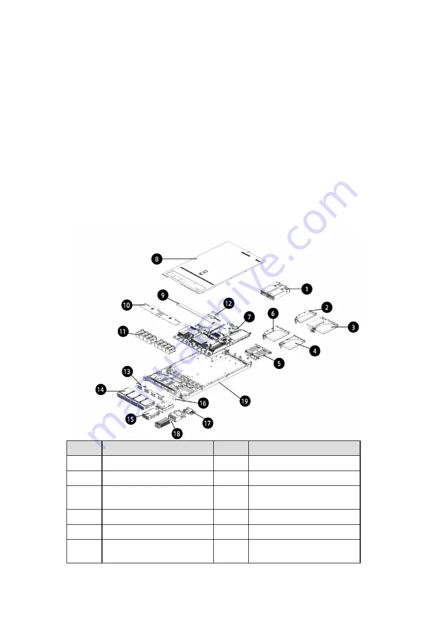
3.5


System Layout 

The layouts of systems with 2.5-inch and 3.5-inch drives are as below: 
Figure 3-13 System Layout with 2.5-inch Drives 


Item 

Item 

PSUs 

11 

Fan Module 

LP PCIe 

12 

Super-Capacitor 

Butterfly PCIe 

13 

Front 2.5-inch Drive 
Backplane 

Right PCIe Module 

14 

Front 2.5-inch Drive Module 

Rear 2.5-inch Drive Module 

15 

Front 2.5-inch Drive Module 

Left PCIe Module 

16 

Front 2.5-inch Drive 
Backplane 

Summary of Contents for NF5180M6

Page 1: ...Inspur Server NF5180M6 User Manual Document Version V1 5 Release Date February 10 2022 ...

Page 2: ...the drive data thoroughly and securely with third party erasing tools The products services or features you purchased may obtain or use some personal data such as email address for alerts and IP address during operation or fault locating There should be user privacy policies in place with adequate measures implemented in accordance with the applicable laws to ensure that users personal data are fu...

Page 3: ...s only used as a guide Inspur shall not be liable for any damage including but not limited to loss of profits loss of information interruption of business personal injury or any consequential damage incurred before during or after the use of our products Inspur assumes you have sufficient knowledge of servers and are well trained in protecting yourself from personal injury or preventing product da...

Page 4: ... you purchased through Inspur direct sales stores call Inspur service hotline 1 844 860 0011 1 760 769 1847 for technical support For your safety please do not disassemble the server s components extend configuration or connect other peripherals arbitrarily You can contact Inspur for our support and guidance Before disassembling the server s components please be sure to disconnect all the cables c...

Page 5: ...nformation that requires special attention to ensure successful installation or configuration Supplementary description of important information Revision History Version Date Description of Changes V1 5 2022 02 10 Added descriptions in Section 4 6 optimized Figure 5 1 8 1 and 8 2 deleted the 1 and 3 DIMM population for dual CPU configuration in memory population guidelines V1 4 2021 08 16 Updated ...

Page 6: ...inch Configuration 13 3 1 4 8 2 5 inch 2 E1 S 2 M 2 Configuration 13 3 1 5 12 2 5 inch Configuration 14 3 1 6 32 E1 S Configuration 14 3 1 7 EVAC Heatsink Server 15 3 1 8 Front Panel Buttons and LEDs 15 3 1 9 Drive Tray LEDs 16 3 2 Rear View 17 3 2 1 1 PCIe 2 2 5 inch 17 3 2 2 2 PCIe 17 3 2 3 3 PCIe 18 3 3 Motherboard View 19 3 4 Motherboard Jumper Introduction 20 3 5 System Layout 21 4 Getting St...

Page 7: ...venting Electrostatic Discharge 63 6 2 Grounding Methods to Prevent Electrostatic Discharge 63 7 Troubleshooting 64 7 1 Hardware Problems 64 7 1 1 Power On Failure 64 7 1 2 No Display 64 7 1 3 Abnormal LED on the Front Panel 65 7 1 4 Stuck in POST Interface or Other Interface 66 7 1 5 PSU LED Off or Illuminates Amber 66 7 1 6 Abnormal Drive Status LED 66 7 1 7 Loud System Fan Noise 67 7 1 8 Alarm ...

Page 8: ...equirements 81 8 10 1 AC Power Supply Requirement 81 8 10 2 DC Power Supply Requirement 81 8 10 3 Recommendations on the AC Power Supply 82 8 10 4 HVDC Power Supply 83 8 10 5 HVDC Power Supply Requirements 83 8 10 6 HVDC Power Supply Suggestions 84 8 10 7 DC Power Supply 84 9 Warranty 85 9 1 Warranty Service 85 9 2 Inspur Service SLA 86 9 3 Warranty Exclusions 87 Appendix 89 Drive Neodymium Conten...

Page 9: ...as power cords power socket if provided with the server etc For your safety and safety of the equipment please do not replace power cords or plugs randomly 5 To prevent electric shocks caused by leakage in the system please make sure that the power cables of the system and peripherals are correctly connected to the earthed grounded outlet Please connect the three core power plug to the three core ...

Page 10: ...ing the equipment and other components into the cabinet only one component can be pulled out from the cabinet through its sliding part at one time Pulling out several components at the same time may cause the cabinet to turn over resulting in serious personal injury 11 Please do not move the cabinet on your own Considering the height and weight of the cabinet the moving of the cabinet should be co...

Page 11: ...nto the socket of network interface controller NIC Before unpacking the product package accessing or installing internal components or touching uninsulated cables or jacks of the modem please disconnect the modem cables In order to avoid damages of electronic components in the equipment caused by electrostatic discharge please pay attention to the followings Please remove any static electricity on...

Page 12: ... brackets During cabinet installation and application please pay attention to the followings After the cabinet has been installed please ensure that the stabilizer feet have been fixed into the rack and supported to ground and all the weight of the rack has fallen to the ground Always load from the bottom up and load the heaviest items first When pulling out components from the rack apply slight f...

Page 13: ...el Xeon scalable processors TDP up to 270 W 3 channels UPI for 11 2 GT s Up to 32 DIMMs with RDIMMs LRDIMMs NVDIMMs BPS memory mirroring and memory hot spare supported Up to 12 hot swap SAS SATA NVMe drives or 32 hot swap E1 S all flash drives at the front Up to 2 2 5 inch SAS SATA SSD at the rear Hot swap OCP 3 0 SFF expansion card 4 onboard Slimline connectors 2 Gen Z connectors and up to 12 dir...

Page 14: ...ch Configuration Up to 10 front 2 5 inch SAS SATA NVMe drives as shown in the figure below Figure 2 1 10 2 5 inch Configuration 2 1 2 4 3 5 inch 2 E1 S 2 M 2 Configuration 3 5 inch drive trays can accommodate 3 5 or 2 5 inch drives Figure 2 2 4 3 5 inch 2 E1 S 2 M 2 Configuration 2 1 3 32 E1 S Configuration 32 front E1 S SSDs as shown in the figure below Figure 2 3 32 E1 S configuration ...

Page 15: ...SATA SAS NVMe drives Up to 12 NVMe drives 32 hot swap E1 S SSDs 4 3 5 inch SAS SATA NVMe drive hot swap 2 M 2 non hot swap 2 E1 S hot swap 4 3 5 inch SAS SATA NVMe drive hot swap 4 2 5 inch SAS SATA NVMe drive hot swap 10 2 5 inch SATA SAS NVMe drive hot swap 8 2 5 inch SATA SAS NVMe drive hot swap 2 E1 S hot swap 2 M 2 non hot swap Rear panel 2 2 5 inch SATA SAS drive hot swap Internal storage Up...

Page 16: ...n Slot Up to 3 PCI Express 4 0 slots for standard PCIe cards 1 PCIe 4 0 x16 full height card and 2 PCIe 4 0 x16 half height cards 1 onboard OCP 3 0 SFF slot for OCP 3 0 card 2 internal SATA M 2 or PCIe x4 M 2 Fan Fan Configuration 8 hot swap N 1 redundant fans 4056 Power Specification 1 1 redundant power supplies 550 W 800 W 1300 W and above Power Input Please refer to the power input on the namep...

Page 17: ...Efficiency Table 2 2 Platinum Power Supplies Rated Power 20 Load 50 Load 100 Load PF 50 Load 550 W 90 94 91 0 98 800 W 90 94 91 0 98 1300 W 90 94 91 0 98 Table 2 3 Titanium Power Supplies Rated Power 10 Load 20 Load 50 Load 100 Load PF 50 Load 800 W 90 94 96 91 0 98 Table 2 4 ErP lot 9 1 EU Regulation 2019 424 Server configurations High end performance configuration Low end performance configurati...

Page 18: ...the performance in active state of the server 40 5 30 4 Table 2 5 ErP lot 9 2 i List of components for additional power allowance High end performance configuration Low end performance configuration CPU Performance 1 socket 10 Perf CPU W 2 socket 7 Perf CPU W 240 31 W 124 81 W Additional PSU 10 W per PSU 10 W 10 W HDD or SSD 5 0 W per HDD or SSD 10 W 10 W Additional memory 0 18 W per GB 367 92 W 4...

Page 19: ...t of components for additional power allowance High end performance configuration Low end performance configuration 25 Gb s and 50Gb s 20 0 W Active Port 50 Gb s 26 0 W Active Port Total power 660 23 W 222 17 W ...

Page 20: ...ration Item 1 E1 S Drive Bay 2 2 M 2 Drive Bay 2 3 Power Button LED 4 UID BMC RST Button LED 5 LEDs 6 USB 3 0 Port 7 USB 2 0 Port 8 VGA Port 9 Quick Release Lever 2 10 3 5 inch Drive Bay 4 3 1 2 4 3 5 inch 4 2 5 inch Configuration Figure 3 2 Front Panel of 4 3 5 inch 4 2 5 inch Configuration Item 1 2 5 inch Drive Bay 4 2 Power Button LED ...

Page 21: ...re 3 3 Front Panel of 10 2 5 inch Configuration Item 1 2 5 inch Drive Bay 10 2 Power Button LED 3 UID BMC RST Button LED 4 Quick Release Lever 2 5 USB 2 0 Port 6 LEDs 3 1 4 8 2 5 inch 2 E1 S 2 M 2 Configuration Figure 3 4 Front Panel of 8 2 5 inch 2 E1 S 2 M 2 Configuration Item 1 2 5 inch Drive Bay 8 2 E1 S Drive Bay 2 3 M 2 Drive Bay 2 4 VGA Port ...

Page 22: ...Figure 3 5 Front Panel of 12 2 5 inch Configuration Item 1 Power Button LED 2 UID BMC RST Button LED 3 LEDs 4 Quick Release Lever 2 5 2 5 inch Drive Bay 12 3 1 6 32 E1 S Configuration Figure 3 6 Front Panel of 32 E1 S Configuration Item 1 E1 S Drive Bay 32 2 Power Button LED 3 UID BMC RST Button LED 4 LEDs 5 Quick Release Lever 2 ...

Page 23: ...e 3 1 Front Panel Buttons and LEDs Icon Item Description 1 Power Button Solid green Power on state Solid orange Standby state Long press 4s to force a shutdown 2 UID BMC RST button Press to turn on or turn off the UID LED blue Long press 6s to reboot the system 3 System Status LED Off Normal Solid red A failure occurs Flashing red A warning occurs 4 Memory Status LED Off Normal Solid red A failure ...

Page 24: ... LED Off Normal Solid red CPU Memory overheats 8 Network Status LED Solid Flashing green Network connected Off No network connection Note It only indicates the working status of onboard network 3 1 9 Drive Tray LEDs Figure 3 8 Drive Tray LEDs Item Description 1 Activity Status LED Solid green Normal Flashing green Read write activities 2 Drive Fault LED Solid red Drive error or failed Solid blue D...

Page 25: ... 3 PSU0 9 System UID Serial Port 4 PSU1 10 UID Button 5 VGA Port 11 OCP 3 0 Module 6 BMC Management Network Port 3 2 2 2 PCIe Figure 3 10 Rear Panel of 2 PCIe Item Item 1 PCIe x16 FHHL 2 The left one for CPU1 and the right one for CPU0 6 USB 3 0 Port 2 2 PSU0 7 Onboard X710 10G Network Ports 3 PSU1 8 System UID Serial Port 4 VGA Port 9 UID Button 5 BMC Management Network Port 10 OCP 3 0 Module ...

Page 26: ... Item 1 PCIe x16 FHHL CPU1 7 USB 3 0 Port 2 2 PCIe x16 HHHL 2 The left one for CPU1 and the right one for CPU0 8 Onboard X710 10G Network Ports 3 PSU0 9 System UID Serial Port 4 PSU1 10 UID Button 5 VGA Port 11 OCP 3 0 Module 6 BMC Management Network Port ...

Page 27: ...nnector 4 GPU_RISER0 Power Connector 30 GPU Power Connector 5 CLR_CMOS Jumper Cap 31 RAID Key Connector 6 GPU0 MID_PCIe Power Connector 32 I2C4_GPU2 Connector 7 Mid Backplane Power Connector 33 PSU0 Connector 8 Rear Backplane Power Connector 4 34 BMC TF Card Slot 9 GPU_RISER1 MID_PCIe Power Connector 35 PCIe0_CPU0 Slot 10 I2 C Connector 4 36 PCIe0_CPU0 Power Connector 11 CLK Connector 37 NCSI Conn...

Page 28: ...0 Connector 49 PCIe0_CPU1 Slot 24 SYS_TF Card Slot 50 Right Control Panel Connector 25 Debug Connector 51 I2 C4_GPU4 Connector 26 SATA Connector 2 52 I2 C Connector 3 4 Motherboard Jumper Introduction It is required to shut down the system and disconnect the power supply during CMOS clearing CMOS clearing will restore default settings of BIOS setup except system date and time See Motherboard View ...

Page 29: ...he jumper cap back to the default pins 1 2 8 Reconnect the power cable and power on the server 3 5 System Layout The layouts of systems with 2 5 inch and 3 5 inch drives are as below Figure 3 13 System Layout with 2 5 inch Drives Item Item 1 PSUs 11 Fan Module 2 LP PCIe 12 Super Capacitor 3 Butterfly PCIe 13 Front 2 5 inch Drive Backplane 4 Right PCIe Module 14 Front 2 5 inch Drive Module 5 Rear 2...

Page 30: ...ystem Layout with 3 5 inch Drives Item Item 1 PSUs 10 Air Duct 2 LP PCIe 11 Fan Module 3 Butterfly PCIe 12 Super Capacitor 4 Right PCIe Module 13 Front E1 S Drive Module 5 Rear 2 5 inch Drive Module 14 Front 3 5 inch Drive Backplane 6 Left PCIe Module 15 Front 3 5 inch Drive Module 7 Motherboard 16 Front M 2 Drive Module 8 Access Panel 17 Chassis 9 Crossbar ...

Page 31: ...or liability for any damage or injury caused by this To reduce the risk of personal injury or damage to the equipment DO secure the mounting ears to the posts firmly to avoid server from moving or sliding out from the cabinet 4 2 Power On Off To power on and off the server press the power button To completely shut down the server press the power button and disconnect the power cable from the serve...

Page 32: ...ectrostatic discharge Do the following prior to installation or maintenance 1 Back up all the data on the server 2 Shut down the server 3 Remove all cables from the system 4 Remove the system from the rack To reduce the risk of personal injury or equipment damage be sure that the rack is adequately stabilized before you extend a component from the rack To reduce the risk of personal injury be care...

Page 33: ...gure 4 1 Removing the Server from the Rack 3 After performing installation or maintenance slide the server all the way back into the rack and secure it in place Figure 4 2 Sliding the Server Back to the Rack ...

Page 34: ...models 4 4 1 Access Panel Replacement To reduce the risk of personal injury from hot surfaces allow the drives and the internal system components to cool before touching For proper cooling do not operate the server without the access panel air duct or fans installed If the server supports hot swap components minimize the amount of time the access panel is open To remove the access panel 1 Loosen t...

Page 35: ...w on the hood latch clockwise to the locked position with a Phillips screwdriver 4 4 2 Air Duct Replacement To reduce the risk of personal injury from hot surfaces allow the machine to cool before touching For proper cooling do not operate the server without the access panel air ducts expansion slot blanks or other blanks installed If the server supports hot swap components minimize the amount of ...

Page 36: ...stall the air duct 1 Lower down the air duct into the chassis until it snaps into place 2 Install the access panel 4 4 3 Crossbar Replacement To remove the crossbar 1 Remove the access panel Refer to Access Panel Replacement 2 Lift up and remove the crossbar Figure 4 5 Removing the Crossbar ...

Page 37: ...risk of personal injury from hot surfaces allow the power supply or power supply blank to cool before touching To remove the super capacitor 1 Remove the access panel Refer to Access Panel Replacement 2 Remove the air duct Refer to Air Duct Replacement 3 Remove the crossbar Refer to Crossbar Replacement 4 Disconnect the cable of the super capacitor 5 Undo the velcro of the super capacitor remove i...

Page 38: ...3 Connect the cable of the super capacitor 4 Install the crossbar 5 Install the air duct 6 Install the access panel 4 4 5 Hot Swap Fan Module Replacement Be sure to wear work gloves during operation to avoid scratches by sharp parts on the equipment To remove the fan module 1 Remove the access panel Refer to Access Panel Replacement 2 Locate the fan module to be replaced The server supports up to ...

Page 39: ... the Fan Module 4 Put the fan module into an antistatic bag To install the fan module 1 Take the new fan module out from the antistatic bag 2 Align the fan connector with the fan slot on the motherboard and lower down the fan module until it snaps into place Make sure the air direction on the fan module is the same as those on the rest fan modules ...

Page 40: ...32 Figure 4 10 Fan Module Direction Figure 4 11 Installing the Fan Module 3 Install the access panel ...

Page 41: ... purchased To remove the OCP 3 0 NIC 1 Loosen the thumbscrew securing the OCP NIC to the server anticlockwise 2 Pull out the OCP 3 0 NIC from the server and put it into an antistatic bag Figure 4 12 Removing the OCP 3 0 NIC To install the OCP 3 0 NIC 1 Take the new OCP 3 0 NIC out from the antistatic bag 2 Insert the OCP 3 0 NIC into the card slot until it snaps into place 3 Tighten the thumbscrew...

Page 42: ...Replacement The illustrations below are for demonstration only The location and direction of the OCP 3 0 NIC may vary depending on the machine configuration you purchased To remove the 2 5 3 5 inch drive 1 Press the release latch to release the lever Figure 4 14 Pressing the Release Latch ...

Page 43: ... it into an antistatic bag For the drive module with the normal drive tray remove the four screws securing the drive to the drive tray to take the drive out of the drive tray Figure 4 16 Removing Drive from the Normal Drive Tray For the drive module with the tool less drive tray press the release tab and then pull the both sides of the drive tray outward to take the drive out of the drive tray ...

Page 44: ...he rear of the drive tray For normal drive tray install and tighten the four screws securing the drive to the drive tray Figure 4 18 Installing 2 5 3 5 inch Drive into the Normal Drive Tray For tool less drive tray align the standoffs on one side of the drive with the holes on the drive tray and then press the other side of the drive until it snaps into place Press the release tab to secure the dr...

Page 45: ...release lever and insert the drive module into the drive bay 4 Close the release lever to lock the drive module in place Verify that the activity status LED on the drive tray is green after powering on the server 4 4 8 E1 S Drive Replacement To remove the E1 S drive 1 Press the release latch to release the lever ...

Page 46: ...essing the Release Latch 2 The lever will pop up automatically Hold the lever and pull the E1 S drive module out of the drive bay Figure 4 21 Pulling Out the E1 S Drive Module 3 Remove the E1 S drive from the drive tray ...

Page 47: ...rive away from the drive tray Figure 4 22 Locations of the Release Tabs on the Intel E1 S Drive Tray Figure 4 23 Removing the Intel E1 S Drive Figure 4 24 indicates the Samsung E1 S drive tray Remove the two screws securing E1 S to the drive tray and pull out the E1 S drive from the tray Figure 4 24 Removing Screws Securing E1 S to the Drive Tray ...

Page 48: ...re 4 26 indicates Intel E1 S drive tray Align the standoffs with the four holes and press down the E1 S drive until it is secured by the release tabs Figure 4 26 Installing Intel E1 S Drive to the Drive Tray Figure 4 27 indicates Samsung E1 S drive tray Install the E1 S drive to the drive tray and install and tighten the two screws securing the drive to the tray ...

Page 49: ... Drive to the Tray 3 Install the drive module into the chassis and close the lever to secure the module in place 4 4 9 M 2 Drive Replacement The server does not support hot swap M 2 drives 1 To remove the M 2 drive of 8 2 5 inch 2 E1 S 2 M 2 Configuration 1 Press the release latch to release the lever ...

Page 50: ...t the M 2 Drive Module 3 Remove the screw avoiding the M 2 drive from moving with a Phillips screwdriver 4 Loosen the four captive screws securing the top and bottom heatsink and the M 2 drive to the drive tray with a Phillips screwdrive and remove the top and bottom heatsink and the M 2 drive away from the drive tray 5 Remove the top heatsink away from the M 2 drive ...

Page 51: ...ve To remove the onboard M 2 drive 1 Open the snap clip securing M 2 One side of the M 2 drive pops up Figure 4 32 Opening the Snap Clip Securing M 2 2 Tilt to pull the M 2 drive out from the drive connector on the motherboard and put it into an antistatic bag ...

Page 52: ...ition the M 2 drive on the drive tray 3 Install the top heatsink and tighten the four captive screws 4 Install and tighten the screw avoiding the M 2 drive from moving The location of the screw avoiding M 2 drive from moving may vary depending on the length of the M 2 drive It is recommended to replace the thermal grease of the M 2 drive to ensure good performance ...

Page 53: ...e module into the drive bay 6 Close the release lever to lock the M 2 drive module in place 3 To install the onboard M 2 drive 1 Take the new M 2 drive out from the antistatic bag 2 Tilt the M 2 drive to insert it into the M 2 drive connector on the motherboard Figure 4 35 Installing the M 2 Drive ...

Page 54: ...the power supply or power supply blank to cool before touching To prevent improper cooling and thermal damage do not operate the server unless all bays are populated with either a component or a blank To remove the PSU 1 Grasp the handle and press the blue release tab to release the PSU 2 Pull the PSU out of the power bay and put it into an antistatic bag Figure 4 37 Removing the PSU To install th...

Page 55: ...lacement To remove the DIMM 1 Remove the access panel Refer to Access Panel Replacement 2 Remove the air duct Refer to Air Duct Replacement 3 Remove the crossbar Refer to Crossbar Replacement 4 Locate the DIMM you want to replace 5 Push the release tabs on both ends of the DIMM slot outward to unlock it 6 Gently lift and remove the DIMM from the slot Figure 4 39 Removing the DIMM 7 Put the DIMM in...

Page 56: ...e slot Use two thumbs together to press both ends of the DIMM straight down into the slot until it snaps into place Figure 4 40 Installing the DIMM 3 Install the crossbar 4 Install the air duct 5 Install the access panel Figure 4 41 DIMM Slot Layout Only DIMMs of the same type could be used in the same machine Detailed DIMM population and combination principles are as follows ...

Page 57: ... QTY CPU0 C1D0 C1D1 C0D0 C0D1 C3D0 C3D1 C2D0 C2D1 C6D1 C6D0 C7D1 C7D0 C4D1 C4D0 C5D1 C5D0 C1D0 C1D1 C0D0 C0D1 C3D0 C3D1 C2D0 C2D1 C6D1 C6D0 C7D1 C7D0 C4D1 C4D0 C5D1 C5D0 2 4 8 12 16 24 32 DDR4 QTY CPU0 CPU1 C1D0 C1D1 C0D0 C0D1 C3D0 C3D1 C2D0 C2D1 C6D1 C6D0 C7D1 C7D0 C4D1 C4D0 C5D1 C5D0 4 4 D B D B B D B D 6 1 D D B D D D D 8 1 D D B D D D D D D 8 4 D D B D D B B D D B D D 8 8 D B D B D B D B B D B...

Page 58: ...rations must contain processors with the same part number To install a faster processor update the system ROM before installing To remove the PHM The heatsink may be hot after the system has been powered down Allow the heatsink to cool down for a few minutes before removing it 1 Remove the access panel Refer to Access Panel Replacement 2 Remove the air duct Refer to Air Duct Replacement 3 Remove t...

Page 59: ... socket Figure 4 47 Removing the PHM 1 Use a protective cover to protect the CPU socket to avoid damaging socket pins after removing the PHM 2 The gold pins on the CPU are fragile and can be easily damaged if touched During removal and installation always keep the gold pins up and DO NOT touch the pins when processor dedicated insertion removal tool CPU tray is unavailable ...

Page 60: ...se the three tabs securing the CPU to the Clip Gently remove the CPU from the Clip and put it into an antistatic bag Figure 4 48 Removing the CPU 8 Gently open the two tabs on one side of the Clip 9 Remove the Clip from the heatsink 10 Lock the lever on the Clip ...

Page 61: ...ns on the CPU are fragile and can be easily damaged if touched During removal and installation always keep the gold pins up and DO NOT touch the pins when processor dedicated insertion removal tool CPU tray is unavailable 1 With the heatsink thermal grease side up align the triangle mark on the Clip with that on the heatsink label and then press the Clip straight down onto the heatsink until the f...

Page 62: ...f the CPU surface area 3 With the gold pins up align the triangle mark on the CPU with that on the Clip Grasp CPU by its two edges and install it into the Clip Make sure the notches of the CPU are aligned with the tabs of the Clip and the CPU is secured in place by the tabs on the four sides of the Clip ...

Page 63: ...r screws securing the PHM to the CPU socket clockwise in the sequence as shown on the heatsink label with a T30 Torx screwdriver 8 Install the crossbar 9 Install the air duct 10 Install the access panel 4 4 13 PCIe Card Replacement To prevent damage to the server or expansion cards power down the server and remove all power cables before removing or installing the PCIe card To prevent damage to th...

Page 64: ...pacitor remove the super capacitor first Refer to Super Capacitor Replacement To remove the PCIe card 1 Remove the access panel Refer to Access Panel Replacement 2 Disconnect all the cables on the PCIe card 3 Lift up the blue latch on the PCIe Riser cage Rotate the latch 180 anticlockwise to unlock it 4 Gently lift and remove the PCIe Riser card assembly with both hands Figure 4 52 Removing PCIe R...

Page 65: ...cement The illustrations below are for demonstration only The location and direction of the RAID controller card may vary depending on the purchased machine configuration To remove the RAID controller card 1 Remove the access panel Refer to Access Panel Replacement 2 Remove the crossbar Refer to Crossbar Replacement 3 Disconnect the SAS cables of the RAID controller card Take a picture of the cabl...

Page 66: ...o screws securing the RAID controller card to the motherboard clockwise with a Phillips screwdriver 4 Connect the SAS cables of the RAID controller card 5 Install the crossbar 6 Install the access panel 4 5 Firmware Update and Configuration For firmware update and configuration refer to BMC Log Collection and Analysis Guide BMC Update Manual BMC Configuration Manual BMC User Manual BIOS Update Man...

Page 67: ...route the cables based on the actual machine configuration Figure 4 55 Cable Routing for 4 3 5 inch 2 E1 S 2 M 2 Configuration Cable Connected Between Connector A Connector B Power Cable MB M 2 Backplane MB FRONT_BP1 Connector J147 2 M 2 BP Power Connector J1 Data Cable RAID Controller Card M 2 Backplane RAID Controller Card Port0 2 M 2 BP SATA0 SATA1 Connector J2 J3 Power Cable MB 4 3 5 inch Back...

Page 68: ...le Connected Between Connector A Connector B Power Cable MB 2 E1 S Backplane MB J69 or J39 2 E1 S BP Power Connector J1 Data Cable MB 2 E1 S Backplane MB SLIM0_CPU0 Connector J80 2 E1 S BP NVMe0 Connector J2 ...

Page 69: ... and reset the system date and time To remove the battery 1 Power down the server and disconnect the power cables from the server 2 Gently slide and remove the server out of the rack 3 Remove the access panel Refer to Access Panel Replacement 4 Remove the PCIe Riser cage 5 Locate the battery on the motherboard 6 Gently press the clip on the battery socket until the battery pops up from the socket ...

Page 70: ... install the battery 1 Take the new battery out from the anti static package 2 Place the new battery into the socket being careful to observe the correct polarity Snap the battery into place Make sure the battery is secured by the clip within the socket 3 Install the PCIe Riser cage 4 Install the access panel ...

Page 71: ...ive component or assembly 6 2 Grounding Methods to Prevent Electrostatic Discharge Several methods are used for grounding Use one or more of the following methods when handling or installing electrostatic sensitive parts Use a wrist strap connected by a ground cord to a grounded workstation or computer chassis Wrist straps are flexible straps with a minimum of 1 megohm 10 percent resistance in the...

Page 72: ...ther the PSUs have failed the PSU LEDs turn green but the power LED on the power button is still orange please call Inspur Customer Service Hotline 1 844 860 0011 1 760 769 1847 or email to serversupport inspur com 2 All the PSU LEDs are green a If all the PSU LEDs are green disconnect the power cables remove and re insert all the PSUs Connect the power cables and power on again to test if the pro...

Page 73: ... the abnormal LED based on Front Panel Buttons and LEDs 1 If the system status LED illuminates red check whether the server is under normal operation If yes log into the BMC Web interface to view the BMC logs For detailed reference document please see Firmware Update and Configuration to check whether there are warnings If yes please record the detailed warning information 2 If the power status LE...

Page 74: ...1 844 860 0011 1 760 769 1847 or email to serversupport inspur com and inform us of the detailed errors 7 1 5 PSU LED Off or Illuminates Amber Symptoms A certain PSU LED on the rear panel is off or illuminates amber when the server is under normal operation Solutions 1 Check if there is normal external power supply Inspect the server for any abnormal appearance such as burning or vulcanization 2 C...

Page 75: ...be plugged in and out online without damage Depending on the RAID level hot plugging a storage drive in the RAID may cause RAID degradation or failure When installing a new drive different RAID controller cards have different policies You may need to log into the RAID management interface for recovery Remove the drive until the drive motor stops completely in order to prevent damage to the motor 7...

Page 76: ...d the specific source 3 If the alarm sound comes from the RAID controller card check the drive fault LED for any warning or log into the RAID management interface for any drive warning and record the detailed warning information if any 4 If the instructions above do not resolve the problem please call Inspur Customer Service Hotline 1 844 860 0011 1 760 769 1847 or email to serversupport inspur co...

Page 77: ... 1 OS Installation Problems Symptoms Unable to load the RAID driver or create partitions larger than 2 T during OS installation C disk usage is too high after OS installation etc Solutions 1 If it fails to load the driver during OS installation check the RAID driver version Go to Inspur website https en inspur com to download the correct RAID driver Some RAID drivers need to be loaded several time...

Page 78: ...ce Hotline 1 844 860 0011 1 760 769 1847 or email to serversupport inspur com 7 2 3 Abnormal Memory Capacity Symptoms The memory capacity displayed in the OS and the physical memory capacity are inconsistent Solutions 1 Check the OS version The supported memory capacity varies with the version of Windows OS Enter BIOS Setup to view the memory capacity If the memory is identified completely the OS ...

Page 79: ...rk cable If the network is normal check the network cable or the switch port if the network is faulty go to Inspur Website https en inspur com to download the latest NIC driver 3 Check whether the NIC can be identified under BMC Web BIOS or Shell and whether the MAC address is correct 4 If the instructions above do not resolve the problem please call Inspur Customer Service Hotline 1 844 860 0011 ...

Page 80: ...C 102 2 F and the air must be non condensing all the time 8 2 Vibration and Shock Resistance Table 8 2 Vibration and Shock Resistance Parameter Condition Requirement Vibration Operating 5 500 Hz 0 21 Grms X Y and Z axis and every direction for 15 minutes Transportation Storage 5 500 HZ 2 2 Grms X Y and Z axis and every direction for 10 minutes Shock Operating On negative and positive X Y and Z axi...

Page 81: ...5 to 93 with maximum dew point at 39 C 102 2 F and the air must be non condensing all the time 8 5 Expanded Operation Temperature The system performance will be impacted when the temperature is not within the specification range Ignore alarm sound of ambient temperature when the temperature is not within the specification range Table 8 5 Expanded Operation Temperature Temperature Specification Not...

Page 82: ...NIC Configu ration 35 when all fans work normall y and 30 when one fan fails 4 3 5 inch NA Supp orted CPU no highe r than 165 W No high er than 205 W NA Rear GPU Configu ration 4 3 5 inch NA Not suppo rted No high er than 165 W T4 and othe r GPU s sup port ed Rear Drive Configu ration 4 3 5 inch SSDs supporte d Not suppo rted No high er than 205 W NA 10 2 5 inch SFF Configurat ion Rear NIC Configu...

Page 83: ...h SFF Configurat ion Rear NIC Configu ration 35 when all fans work normall y and 30 when one fan fails 12 2 5 inch NA Supp orted CPU no highe r than 165 W No high er than 205 W NA Rear GPU Configu ration 12 2 5 inch NA Not suppo rted No high er than 165 W T4 and othe r GPU s sup port ed Rear Drive Configu ration 12 2 5 inch SSDs supporte d Not suppo rted No high er than 205 W NA 32 E1 S Configurat...

Page 84: ...5 W and high er Not sup port ed Rear GPU Configu ration 30 No fan failure is allowe d 4 2 5 inch NA Not suppo rted 205 W and high er T4 and othe r GPU s sup port ed Rear Drive Configu ration 35 No fan failure is allowe d 4 2 5 inch SSDs supporte d Not suppo rted 205 W and high er NA 8 8 Operational Requirement This section specifies the requirements of temperature humidity organisms chemical mater...

Page 85: ...hemical reactions may occur due to long term contact between these mixed corrosive gas pollutants or pollutants of one single corrosive gas and other environmental factors such as temperature or relative humidity which may pose a risk of IT equipment failure from corrosion and damage circuit boards of IT equipment and system component units with weak oxidation resistance This article specifies the...

Page 86: ... An environment in which there is high probability that corrosive attack will occur GX severe 2000 Å month 2000 Å month An environment in which only specially designed and packaged equipment would be expected to survive See Table 8 8 for the requirements on the copper and silver corrosion rates Table 8 8 Concentration Limitation on Corrosive Airborne Contaminants in a Data Center Group Gas Unit Co...

Page 87: ...ts for Concentration of Mechanically Active Materials Mechanically Active Materials Unit Concentration Sand mg m3 30 Suspending dust mg m3 0 2 Dust deposit mg m2 h 1 5 To meet these requirements take the following measures in the server room Use dustproof materials on the ground wall and ceiling of the server room Adopt few or no windows design in the server room and use dustproof materials for ou...

Page 88: ...trified railways industrial radiation substations and high voltage transmission lines The interference effect of other equipment in the server room must comply with relevant standards and regulations Take measures to shield and isolate natural noise such as atmospheric noise and solar radio noise when necessary To avoid damage to the system take ESD protection measures For more information on elec...

Page 89: ...e in the same phase as the mains supply The time used for switching between the UPS and the mains supply should be less than 8 ms Otherwise the server will reboot or reset 8 10 2 DC Power Supply Requirement DC power supply system should work under nominal voltage of 48 V 270 V and 336 V When determining the power distribution capacity in the server room consider the working current and fault curre...

Page 90: ... the long term load cables can be routed by stage AC DC conducting wires should be flame retardant and be routed according to the Code for fire protection design of tall buildings GB50045 8 10 3 Recommendations on the AC Power Supply Recommendations on the AC power supply are as follows Use a voltage stabilizer or voltage regulator to respond to unstable voltages Use a voltage regulator in the fol...

Page 91: ...em capacity and backup time the cell voltage can be selected from 2 V 6 V or 12 V The insulation monitoring device acts properly if a ground fault occurs or the insulation resistance is 28 kΩ lower than the set value The HVDC system is protected against overcurrent and short circuits and can be manually or automatically restored after overcurrent or short circuits are rectified Over and under volt...

Page 92: ...ring Connect the DC output positive pole to terminal N of the equipment power cable Connect the DC output negative pole to terminal L of the equipment power cable DC system is strictly forbidden to be grounded The upstream input terminal of the power supply system is equipped with a surge protection device to protect the system against a minimal voltage surge of 10 700 us 5 kV and a minimal curren...

Page 93: ...e technical support can be obtained through hotline e mail and Service Portal 1 Through hotline and e mail support Inspur engineers help customers diagnose the cause of malfunction and provide solution Service Portal 1 provides access to firmware customized update files and related manuals for Inspur products Customer may also access the Service Portal 1 to submit Return Material Authorization RMA...

Page 94: ...f a problem with customer product cannot be resolved via hotline and e mail support and a replacement part is required Inspur will ship out replacement part s in advance within one 1 business day Customer should return defective part s within five 5 business days after receiving the replacement s Inspur will cover one way shipment via ground Standard Replacement When a hardware failure happens cus...

Page 95: ... or maintenance Virus infection Loss or damage in transit which is not arranged by Inspur The product has been modified or serviced by non authorized personnel Any damage to or loss of any personal data programs or removable storage media The restoration or reinstallation of any data or programs except the software installed by Inspur when the product is manufactured Any consumable parts such as b...

Page 96: ...r otherwise even if Inspur has been advised of the possibility of such damage and whether or not any remedy provided should fail of its essential purpose 1 Service Portal availability is subject to customer type and customer location Please contact your Inspur representative to learn more 2 Not all SLA offerings are available at all customer locations Some SLA offerings may be limited to geolocati...

Page 97: ...imarron 6T 8T Evans Kestrel MakaraBP MakaraPLUS Mobula MobulaBP Skybolt Tatsu Table A 1 2 Seagate Drive Neodymium Content Reference Product Series Name Neodymium Content Range 5 g 5 g 25 g 25 g Rainier Libra He10 Leo A Vela A Vela AP Hs14 Leo B Table A 1 3 Seagate Drive Neodymium Content Reference Product Series Name Neodymium Content Range 5 g 5 g 25 g 25 g AL14SE Lite AL15SE AL14SX ...

Page 98: ...Power Management Interface AES Advanced Encryption Standard New Instruction Set AI Artificial Intelligence AOC Active Optical Cables API Application Program Interface ARP Address Resolution Protocol B BIOS Basic Input Output System BMC Baseboard Management Controller C CE Conformite Europeenne CLI Command Line Interface CMOS Complementary Metal Oxide Semiconductor Transistor CPLD Complex Programmi...

Page 99: ...iguration Protocol DIMM Dual Inline Memory Modules DNS Domain Name System DVD Digital Video Disc F FMA Failure Mode Analysis FRU Field Replaceable Unit FTP File Transfer Protocol FW Firmware G GPU Graphics Processing Unit GUI Graphical User Interface H HBA Host Bus Adapter HCA Host Channel Adapter HDD Hard Disk Drive HTML Hyper Text Markup Language HWRAID Hardware Redundant Arrays of Independent D...

Page 100: ...all Computer System Interface J JTAG Joint Test Action Group K KVM Keyboard Video Mouse L LAN Local Area Network LCD Liquid Crystal Display LED Light Emitting Diode LRDIMM Load Reduced Dual In Lane Memory Module M MLAN Music Local Area Network N NCSI National Communication System Instructions NEMA National Electrical Manufacturers Association NFPA National Fire Protection Association NIC Network I...

Page 101: ...onent Interconnect PCIe Peripheral Component Interconnect express PDU Power Distribution Unit PFR Platform Firmware Resilience PHM Processor Heatsink Module PHY Physical PMBus Power Management Bus POST Power On Self Test PSU Power Supply Unit PXE Pre boot Execution Environment R RAM Random Access Memory RAID Redundant Arrays of Independent Drives RDIMM Registered Dual In line Memory Module RH Rela...

Page 102: ...etwork Management Protocol SOL Serial Over LAN SSD Solid State Disk SSH Secure Shell SWRAID Software Redundant Arrays of Independent Drives T TCG Trusted Computing Group TCM Trusted Cryptography Module TCO Total Cost of Ownership TDP Thermal Design Power TPCM Trusted Platform Control Module TPM Trusted Platform Module U UEFI Unified Extensible Firmware Interface UID User Identification UPI Ultra P...

Page 103: ...95 USB Universal Serial Bus V VGA Video Graphics Array VLAN Virtual Local Area Network X XDP eXtend Debug Port ...

Reviews: