— 13 —
Carrier Strength and Alarm
(Menu Screen 5)
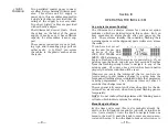
The upper line of this
screen displays signal
strength of the RF carri-
er. The
RF
numerical
value is the level at the
antenna input in dBuV, and defines a range between 0dBuV
(1 microvolt) and 75dBuV (about 5 millivolts). The bargraph
readout gives an analog display of levels in the range of
10dBuV to 75dBuV. The signal strength display does not
refer to the dB scaling above the display, which is used only
for audio level measurements in Menu Screen 7.
The lower line of the screen is labeled
LOSIG:
and has a
pair of tic marks off to the right. Push the knob and
LO
, will
begin to blink, along with the left-hand tic mark. Turn the
knob to position the left tic mark anywhere beneath the
RF
bargraph. The tic mark level in dBuV is also displayed.
When the
RF
bargraph falls below this tic mark during nor-
mal receiver operation, it initiates a carrier-loss alarm and
causes
LOW SIGNAL
to flash on the LCD screen.
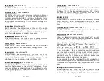
As a starting point, you might set the left, carrier-loss trig-
ger point about half the way down from the top of the
RF
bargraph, as shown in the illustration. This should allow
for typical signal fading over the receive path, but will still
alert the user to a valid carrier loss or major transmitter
power problem.
Push the knob again.
HI
and the right-hand tic mark will
blink. Turn the knob to set that tic mark to a point that the
carrier level must come back up to for the alarm to reset,
maybe a few segments above the left tic mark. Push the
knob again to set these points in memory and to release the
menu.
The alarm flashes
LOW SIGNAL
on the front-panel LCD and
activates the rear-panel
L
(low signal) terminal. Refer to
Pages 8 and 18 for using and programming this terminal.
Signal Quality Readouts
(Menu Screen 6)
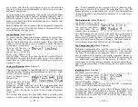
SN:
is a first-order approximation of the signal-to-noise
quality of the demodulated program with respect to total
channel noise. This measurement takes into account fac-
— 14 —
tors that involve multiple channels and other interference
factors. The metered range is 0dB to 20dB.
CN:
is the OFDM carrier-to-noise ratio. This defines the dy-
namics of the OFDM subcarrier group signal level between
its on and off (null) states. The metered range extends from
0dB to 54dB.
The
RF
,
SN
and
CN
numerical values are handy metrics when
installing a rooftop antenna. In locating and aiming the an-
tenna, do everything you can to maximize the numbers.
Program Audio Metering
(Menu Screen 7)
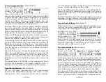
Menu Screen 7 is a left- and right-channel bargraph presen-
tation of the stereo program audio level. Meters are peak-
responding with a floating peak-hold function.
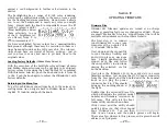
The
0dB
level of a DAB
broadcast corresponds
to 0dBFS of the incoming
digital audio feed. This
is denoted by the large
block opposite the
0dB
marking on the panel. The meter
re1, +2 and +3dB above 0dB. Below 0dB the scale is
linear in 0.5dB steps to –6dB, then in 1dB steps to –20dB,
and from there in 2dB steps to –40dB.
The Audio Loss Alarm
(Menu Screen 8)
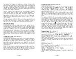
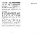
Navigate to this Menu
Screen and push the
knob.
Audio Loss
will
begin blinking. Turn the
knob to dial-in a desired
alarm delay time; that is, the time in seconds between the
onset of ‘dead air’ and a front-panel indication and rear-
panel Audio Loss tally. The delay may be programmed in
one-second increments between
1s
and
120s
(two minutes).
Turn the knob completely counterclockwise to
Off
if you
want to deactivate the alarm altogether. After setting this
delay time interval, push the knob again to lock-in your set-
ting. This action will cause the word
Threshold
to blink.
The trip point of the Audio Loss alarm is adjustable. The
numerical value is the peak level that the program must fall
below, and remain below, throughout the programmed de-


