SCAMAX
®
2600/4000
Tech. Manual 06/2002
T-51
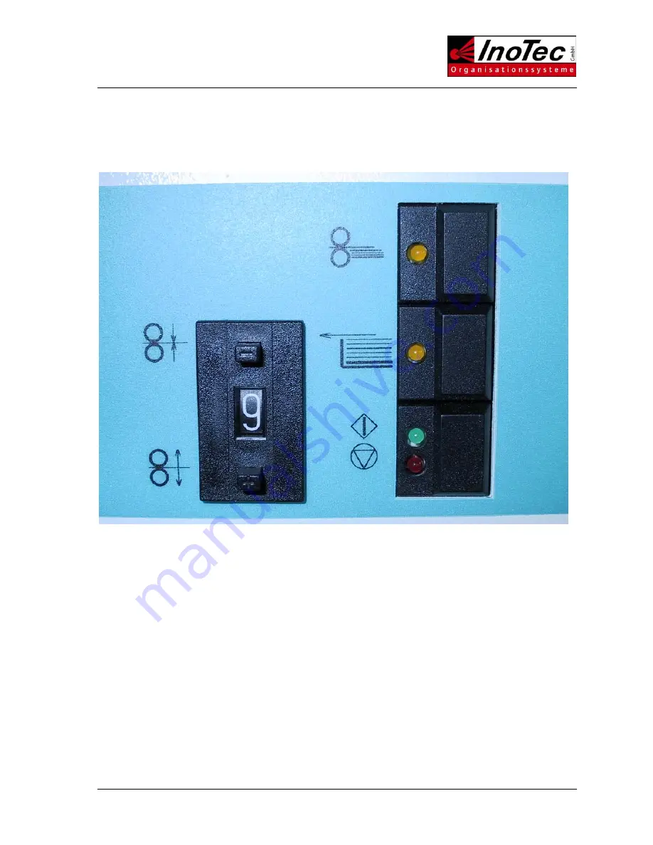
3.11 Operator Panel
The operator panel contains three push button switches with one or two integrated LED's and one BCD-
switch.
The push button switches are soldered onto a circuit board, which is mounted behind the front panel. The
BCD-switch is of the snap-in type. It is connected to the circuit board via a plug and cable.
In addition the circuit board has a two position switch (HI/LOW), which is used for various service
settings.
The circuit board is connected to the I/O board via a ribbon cable. Static signals of a 5V TTL-level are
transmitted.
Summary of Contents for SCAMAX 2600
Page 7: ...SCAMAX 2600 4000 Tech Manual 06 2002 T 7...
Page 12: ...SCAMAX 2600 4000 Tech Manual 06 2002 T 12...
Page 14: ...SCAMAX 2600 4000 Tech Manual 06 2002 T 14...
Page 16: ...SCAMAX 2600 4000 Tech Manual 06 2002 T 16 Illustration of optical reduction...
Page 34: ...SCAMAX 2600 4000 Tech Manual 06 2002 T 34...
Page 49: ...SCAMAX 2600 4000 Tech Manual 06 2002 T 49...
Page 56: ...SCAMAX 2600 4000 Tech Manual 06 2002 T 56...
Page 62: ...SCAMAX 2600 4000 Tech Manual 06 2002 T 62...
Page 66: ...SCAMAX 2600 4000 Tech Manual 06 2002 T 66...


