25
CPS 220/64/SV
Montage- und Betriebsanleitung
CPS 220/64/SV
Mounting and Operating Instructions
Jetzt kann die Haube des Gehäuses abgenommen wer-
den. Anschließend müssen die sechs Schrauben und die
Frontabdeckung entfernt werden, um das Gehäuse an der
Wand zu befestigen.
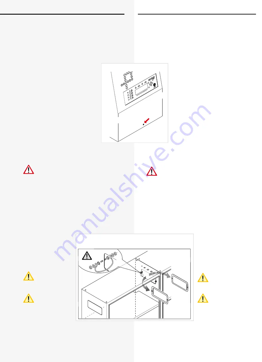
6.1.3. CPUSB 220 / 64 / 24V
Nach dem Auspacken entfernen Sie im
liegenden Zustand die beiden Schrau-
ben in Höhe des Displays, anschließend
ist die vordere Schraube am Gehäuse zu
lösen. Jetzt kann die Haube des Gehäuses
abgenommen werden. Die angeschlos-
sene Erdungsleitung ist steckbar auf der
Gehäuserückwand befestigt.
Vor dem Schließen des Gehäuses ist die
Erdungsleitung wieder mit der Gehäuse-
rückwand zu verbinden.
6.2. Batterie
Bitte überprüfen Sie die gelieferten Batterien, Polverbin-
der und Batteriekabel auf Vollständigkeit und mechani-
sche Beschädigungen.
Vor Anschluss der Batterien sind die Batteriesiche-
rungen F1 und F2 zu entfernen. Die entsprechen-
den Sicherheitsbestimmungen betreffend hoher
Gleichspannung sind zu beachten. Erst wenn die Installa-
tion des gesamten CPS-Systems abgeschlossen ist, sind
die Batteriesicherungen F1 und F2 einzusetzen
siehe 7. Inbetriebnahme - Seite 61
Die Batterien gemäß der folgenden Abbildungen in den
Schrank einsetzen, mit den Polverbindern verschalten
und die Schutzkappen auf die Pole setzen. Für die Monta-
ge von Batterien im 2m Standschrank oder auf Batteriege-
stellen beachten Sie bitte die gesonderte Dokumentation.
Für die Montage von Bat-
terien in zwei oder mehr
Batterieschränken sind für
die Verdrahtung die seitli-
chen Flanschplatten gemäß
Zeichnung zu entfernen.
Die Batterieschränke
sind mit den mitge-
lieferten Erdungslei-
tungen zu verbinden.
Die Batteriehinweise
sind Bestandteil der
Bedienungsanleitung
und müssen aufbewahrt
werden. Weitere Hinweise
zur Inspektion und Pflege
der wartungsfreien Batterien
entnehmen Sie den mitge-
lieferten Batterieinstruktionen.
Die Flanschplatten bei Bedarf entfernen.
Remove cover plate if required.
The cover can now be removed. The six screws and the
front cover now have to be removed so that the housing
can be fastened to the wall.
6.1.3. CPUSB 220/64/24 V
After unpacking, and with the device in
the horizontal position, remove the two
screws at the height of the display and
detach the front screw on the housing. The
housing hood can now be removed. The
attached earth wire can be inserted and
fastened to the housing rear wall.
Before closing the housing, reconnect the
earth wire to the rear wall of the housing..
6.2. Battery
Please check the supplied batteries, connector and batte-
ry cable for completeness and mechanical damage.
Before connecting the batteries, battery fuses F1
and F2 must be removed. The relevant safety
regulations concerning high DC voltage must be
observed. The battery fuses F1 and F2 may be inserted
only when installation of the entire CPS system is comple-
te
see 7. Commissioning on page 61
Insert the batteries in the cabinet as shown in the fol-
lowing diagrams, attach them to the connectors and
place the protective caps over the pins. Please see the
separate documentation for fitting batteries in the 2 m
upright cabinet or onto battery racks.
For fitting batteries in two
or more battery cabinets,
the side flange plates must
be removed to enable wiring
as shown in the diagram.
The battery cabinets
must be connected
with the supplied
earthing cables.
The battery instruc-
tions are part of the
operating instructions
and must be kept in a safe
place. Additional information
on inspection and care of the
maintenance-free batteries
can be found in the battery
instructions supplied.


