background image


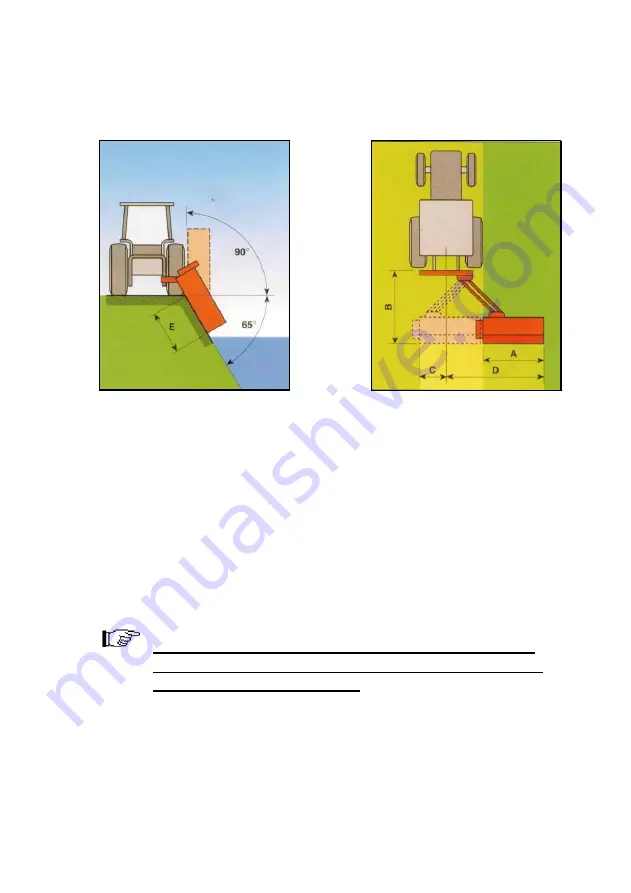
Fig. 3 


Fig. 4 


2.3


Optional equipment 


According  to  the  working  conditions  we  recommend  the  following 
additional quipment: 


Y blade (for cutting material till max. 3 cm in diameter) 


Hammers (for cutting material till max 5 cm in diameter) 


Maximal thickness of the material depends on the sort 
and hardness of the wood. Up-mentioned diameters are 
valid for the fresh wood only.


Summary of Contents for MKM

Page 1: ... OW WE ER R M MK KM M O OP PE ER RA AT TI IN NG G I IN NS ST TR RU UC CT TI IO ON NS S S SP PA AR RE E P PA AR RT TS S L LI IS ST T I IT T I IS S M MA AN ND DA AT TO OR RY Y T TO O R RE EA AD D A AN ND D F FO OL LL LO OW W T TH HE ES SE E I IN NS ST TR RU UC CT TI IO ON NS S B BE EF FO OR RE E C CA AR RR RY YI IN NG G O OU UT T A AN NY Y O OP PE ER RA AT TI IO ON N ...

Page 2: ...machine 17 5 Transport and attachment of the machine 18 Transport to the customer 18 Attachment and detachment from the tractor 19 Fitting the PTO shaft 20 Stability of the tractor 21 6 Adjustment and setting up 22 Regulating the height of cut 22 Belt tension adjustment 23 7 Operating 24 8 After the job done 27 Cleaning 28 9 Maintenance 29 Belt tension control 30 Oil level control 31 Control of bo...

Page 3: ...echnical characteristics and after sales services go together with your choice For eventual questions our stuff is always at your disposal We will specially respect your suggestions and observations that can be of a great help for future development of the machine Through all the past of our company experiances from the praxis represent a basement of development and innovations INO d o o General M...

Page 4: ...the operator s other people s and animal s safety apart from the correct functioning of the machine In case of doubt do not experiment call INO after sales service instead or a specialized INO dealer It is mandatory to read these instructions to understand the operating of the machine In the case of re sale of the machine it is necessary to give these instructions to the new owner A meaning of dec...

Page 5: ...DIRECTIVES DIRECTIVE MACHINE 89 392 CEE AND FOLLOWING ADDITIONS 91 368 CEE 93 44 CEE 93 68 CEE AND 2006 42 CEE HARMONISED STANDARDS APPLIED IN ORDER TO VERIFY COMPLIANCE WITH DIRECTIVES SIST EN 292 1 SIST EN 292 2 SIST EN 745 A producer can ensure normal operating of the machine only with use of original spare parts INO is not responsible for any damage or injuries if the user doesn t consider the...

Page 6: ... use of non genuine spare parts Non respecting these rules Overloading of the machine see Table nr 1 limited values 1 3 Identification of the machine Each machine is fitted with an identification plate with the following data producer and address CE sign name of the machine type weight identification number and year of production Fig 1 MULČER MKM 190 693 kg 2012 123 ...

Page 7: ...linkage 5 rear roller 6 support foot 7 skid 8 sliding tubes 9 mower arm 2 1 Noise The sound level of this machine as measured at the operator s ear ranges from 70 to 90 dB when the rear window of tractor is open We recommend the use of ear protectors 4 9 6 7 1 5 3 2 8 ...

Page 8: ...40 540 540 540 Weight kg 522 575 693 748 810 linkage cat II II II III II III II III Angle 90 65 90 65 90 65 90 65 90 65 Y bl nr 32 40 48 56 60 hammer nr 16 20 24 28 30 width cm 153 183 213 248 263 height cm 100 100 100 100 100 Transp length cm 165 165 165 165 165 Tab 2 Working width in different positions MKM Unit MKM 130 MKM 160 MKM 190 MKM 225 MKM 245 A cm 132 162 192 227 242 B cm 200 200 200 20...

Page 9: ...end the following additional quipment Y blade for cutting material till max 3 cm in diameter Hammers for cutting material till max 5 cm in diameter Maximal thickness of the material depends on the sort and hardness of the wood Up mentioned diameters are valid for the fresh wood only ...

Page 10: ...achine Reading instructions among operating is too late 4 Security and warning decals on the machine are very important Respect them always 5 Even when using the machine correctly stones or other objects may be thrown on a long distance Therefore nobody must stand within the danger area Special attention must be paid when working near roads or buildings 6 Use tractor with the cabin 7 Whenever usin...

Page 11: ...achine 17 Keep a safety distance from drive parts outside of the machine PTO shaft hydraulic pipes 18 Before leaving the tractor with the machine attached disconnect the tractor put the machine steadily on the ground with the hydraulic lift apply the hand brake and if the ground is steeply slooping wedge the tractor Take out the starting key 19 Do not enter the zone between the tractor and the mac...

Page 12: ...e road conditions PTO drive 1 Use only PTO shafts with all guards as directed by the producer 2 All guards on PTO shaft must be in good order 3 Take care that all guards on the PTO shaft are in proper position during transport or operating Respect the producer s instructions 4 The PTO shaft must be assembled or diassambled only with the engine stopped and the starting key removed 5 The guards of t...

Page 13: ...and the key removed 13 If the PTO shaft is damaged immediately stop with any operating Hydraulic system optional equipment 1 Take care Hydraulics is under very high pressure 2 At connecting the pipes on the tractor check that the pressure is not too low 3 We recommend that an official service tests the pipes before operating and than at least ones per year Damaged or worn pipes should be replaced ...

Page 14: ...ve the starting key after you stopped the tractor 3 Periodically check that bolts and nuts are tighten properly 4 At maintaining it is sometimes necessary to lift the machine It is mandatory to put under the machine an appropriate support to avoid falling the machine at eventual damage on hydraulics 5 Use the gloves and appropriate tools at changing sharp parts of the machine to avoid injuries 6 U...

Page 15: ...n operations 2 Keep at a safety distance from the machine to avoid the risk of projection of objects 3 Never remove the guards while the parts of the machine are moving It is dangerous to injure the hands 4 Keep at a safety distance from the machine to avoid the risk of cutting the feet 5 It is forbidden to mount on the machine because of the risk of fall ...

Page 16: ... of guards Fig 5 1 PTO shaft shield 2 belt shield 3 warning decals 4 Side guard 5 flaps 6 horisontal blockade 7 vertical hydraul blockade 8 frame guard 9 mechanic breakaway 10 floating 1 5 2 4 3 6 4 7 8 9 7 10 ...

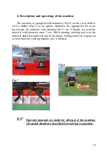
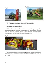
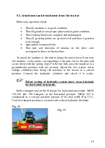
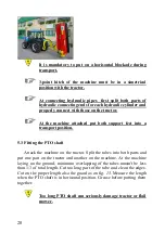
Page 17: ...rk for material with diameter till 5 cm Y blades are used for material with diameter max 3 cm While rotating working tools cut the material and lift it under the top of the frame Falling material is again cut several times by rotating hammers or Y blades Fig 6 Fig 7 Fig 8 Operator manuals are made for all types of the machine All special details are described for each type separately ...

Page 18: ...use special holes on the frame Fig 11 Check that all nuts and bolts are fixed and tightened Specially check the bolts and nuts for the working blades and on connection arm frame Fig 11 1 Fig 11 According to the dimensions of the machine and different possibilities of the transport the machine can be sent split assembled on the pallet or in the box 90 65 1 ...

Page 19: ...o the points corresponding to the pins Insert the pins and secure them with the spring clips Fit the top link raise the machine to a perpendicular position with the ground Adjust the two tractor lower linkage stabilizers thus fixing the machine to the tractor in a central position Connect the hydraulic cylinders and check if it works Before testing of hydraulic system move away blockade for horiso...

Page 20: ...into a transport position 5 3 Fitting the PTO shaft Attack the machine on the tractor Split the tubes into both parts and put one part on the tractor and another on the machine At the machine laying on the ground minimum overlapping of the tubes mustn t be less than 1 3 of total length Cut too long part of the tube and clean the edges Cut on the proper length also the guard as on fig 15 Measure th...

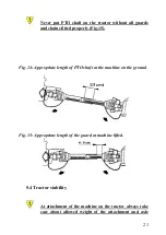
Page 21: ...operly Fig 15 Fig 14 Appropriate length of PTO shaft at the machine on the ground Fig 15 Appropriate length of the guard at machine lifted 5 4 Tractor stability At attachment of the machine on the tractor always take care about allowed weight of the attachment and axle 1 3 cevi ...

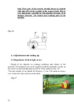
Page 22: ...rt of the machine Fig 16 6 Adjustment and setting up 6 1 Regulation of the height of cut Height of cut depends on working conditions and volume of the material The height of cut can be regulated with the hydraulic system on the tractor or and with adjusted rear roller of the machine Fig 18 The min height of cut should be between 1 3 cm The machine always run on the rear roller and not on the skids...

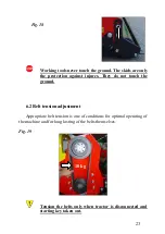
Page 23: ...st injures They do not touch the ground 6 2 Belt tension adjustment Appropriate belt tension is one of conditions for optimal operating of the machine and for long lasting of the belts themselves Fig 19 Tension the belts only when tractor is disconnected and starting key taken out 10 kg ...

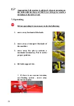
Page 24: ... 5 cm 7 Operating Before operating it is necessary to do the following 1 move away horisontal blockade 2 move away a transport blockade of the machine 3 move away the pin to activate a mechanic breakaway Put it on the proper position 4 lift both support feet 5 If there is an uneven terrainn use floating system move away the inserted plate ...

Page 25: ...ediately stop the cardan shaft check the rotor shaft and change damaged and missing parts see chapter 9 6 If the rotor shaft after changing still runs unequally it is necessary to balance it contact servicing dep INO Before starting lift the machine for 10 cm After starting the machine put it on the ground into the working position gently It is strongly forbidden to activate PTO shaft if the machi...

Page 26: ...ging it Fig 22 During turning lift the machine Very important part of equipment is mechanic breakaway Fig 24 At touching the stone or other obstacle mechanic breakaway allows that body of the machine moves away to avoid injury At touching any barrier stop immediately and drive back that springs turn back into normal position lift the machine bypass the obstacle and continue with normal work 1 2 ...

Page 27: ... may render driving difficult and damage the machine itself During transport the machine must be always in the transport position PTO shaft must be disconnected during transport At disconnecting the machine respect the warning rules for connecting the machine Before disconnection of the machine put on a pin Fig 25 2 Check the condition of the rotor shaft working blades and if they are tightened we...

Page 28: ...ody of the machine Put the support feet into the standing position and lift down the machine Disconnect the PTO shaft and put it on the hook Fig 25 1 Disconnect the machine from the tractor 3 point hitch Fig 25 Fig 26 At disconnecting the machine from the tractor block the rear roller with a piece of wood for stability of the machine 8 1 Cleaning To avoid any corrosion clean the machine after each...

Page 29: ...connected PTO engine off and starting key out A time of maintenance is defined according to the normal use of the machine If the machine is used in very hard conditions the time between maintenance operations must be shorter Take care that grease nipples on the machine are always clean After each maintenance operation check that all guards are fitted on the proper place ...

Page 30: ...the bolt for tensioning Fig 30 1 the nut and the bolts under gearbox Put the belt shield back on the machine Appropriate belt tension is achieved when at pressing on the belts with the force of 100 N i e 10 kg we reach a deviation of the belt 1 5 cm After first two hours of work check the belt tension and if necessary tighten the taper lock Fig 27 1 2 Fig 28 Fig 29 Fig 30 1 5 1 1 4 ...

Page 31: ...op of gearbox for filling in Fig 31 1 For pouring in use a funnel Pour in the oil till the level of the control plug on the gearbox Fig 31 1 A plug for oil control is placed on the rear side of the gearbox Fig 31 2 Slika št 31 9 3 Control of bolts Fig 32 Take special care that the bolts Fig 32 1 are tightened well 1 2 1 ...

Page 32: ... round At greasing use the glaves After greasing always wash your hands Use type LIS 3 for greasing 9 4 Greasing The machine has the following greasing points Left and right bearing on the rotor shaft Fig 35 7 8 Left and right bearing on the rear roller Fig 36 9 10 Pins of the arm Fig 33 1 3 Fig 34 4 5 Connection Fig 34 6 End parts of PTO shaft Hydraulic cylinder Fig 37 Lifting system Fig 38 1 2 B...

Page 33: ...33 Fig 33 Fig 34 Fig 37 Fig 38 1 Fig 34 6 Fig 35 Fig 36 Fig 38 2 5 9 4 10 7 8 3 1 2 ...

Page 34: ...the frame and the 3 point hitch are in good condition That all parts are greased well 3 On every 100 hours we recommend to Check and grease the PTO shaft 4 On every 12 months we recommend to Change the oil in the gearbox and check the belts tension 9 6 Replacement of working tools Immediately after you notice that working tools are damaged change them If it is necessary to change only few blades a...

Page 35: ...r Put the machine on a dry and flat ground 9 8 Demolition when out of order If the machine is out of order all its parts that might cause dangers have to be made inoffensive Materials forming the machine that have to undergo a differentiated division are steel mineral oil rubber plastic All the above mentioned operations and the disposal have to be carried out in total respect of the present provi...

Page 36: ...amages and repair the machine Noise in the gearbox Lack of oil Fill till level Worn gears Replace Worn bearings Replace Vibrations Broken or worn flails Replace Unbalanced rotor Balance or replace Worn rotor bearings Replace Excessive backlash in joints Worn pins Replace Damaged bearings Dirty or ungreased bearings Clean and grease Violant impact on the ground when the machine is lowered Lower it ...

Page 37: ... parts min 7 years after the sael of the machine At ordering the spare parts always add the following details type of the machine serial number and year of the production All data are on the identification plate See the sample order below machine type Serial nr year Pos Part nr name pc f mower MKM 333 2009 4 017943 gearbox 1 Servicing Tel 386 0 7 49 59 233 0 7 49 59 306 ...

Page 38: ...38 A ...

Page 39: ...39 B ...

Page 40: ... 20 010224 4 4 4 4 4 18 WASHER 30 010227 17 17 17 17 17 19 WASHER 10 010232 2 2 2 2 2 20 WASHER 12 010233 6 6 6 6 6 21 WASHER 14 010234 4 4 4 4 4 22 WASHER 16 010235 4 4 4 4 4 23 BOLT M 10x 30 010259 1 1 1 1 1 24 BOLT M 10x 35 010260 7 7 7 7 7 25 BOLT M 10x 40 010261 1 1 1 1 1 26 BOLT M 12x 35 010270 9 9 9 9 9 27 BOLT M 16x 30 010280 4 4 4 4 4 28 BOLT M 14x 35 010325 14 14 14 14 14 29 PIN R3 01032...

Page 41: ...90 010749 1 FLAP BAR 225 011013 1 FLAP BAR 245 017257 1 50 BEARING 1309 011054 2 2 2 2 2 51 PIN 8 011598 2 2 2 2 2 52 WASHER 12 011654 4 4 4 4 4 53 GREASE NIPPLE FLAT 011669 8 8 8 8 8 54 REAR ROLLER130 110007 1 REAR ROLLER 160 011733 1 REAR ROLLER 190 011734 1 REAR ROLLER 225 011735 1 REAR ROLLER 245 016956 1 55 HAMMER 011806 16 20 24 28 30 56 BOLT M 14x 40 011835 6 6 6 6 6 57 PULLEY 130 80 3 0119...

Page 42: ...4 28 32 79 ROTORwith bear balanc 017456 1 ROTOR with bear balanc 017458 1 ROTOR with bear balanc 017368 1 ROTOR with bear balanc 017370 1 ROTOR with bear balanc 017252 1 80 BUSHING CU 017864 2 2 2 2 2 81 BOLT M 30x190 8 8 017991 3 3 3 3 3 82 NUT M 30 017993 9 9 9 9 9 83 WASHER 12 019016 4 4 4 4 4 84 WASHER 12 019021 6 6 6 6 6 85 CONNECT 1 MK S 019681 1 1 1 1 1 86 LIFTING MECH R 019687 1 1 1 1 1 87...

Page 43: ...AME MKM 245 020974 1 106 BOLT M 12x 40 020671 6 6 6 6 6 107 BLOCKADE 020849 1 1 1 1 1 108 BOLT M 10x 55 021046 1 1 1 1 1 109 GEARBOX 021552 1 1 1 1 1 110 WASHER 021671 1 1 1 1 1 111 BOLT M 10x 60 021672 1 1 1 1 1 112 GEARBOX PLATE 021955 1 1 1 1 1 113 BOLT M30x250 022557 4 4 4 4 4 114 BLOCKADE 022559 2 2 2 2 2 115 BOLT M 14x 35 022564 2 2 2 2 2 116 ROLLER BRACKET L 022735 1 1 1 1 1 117 ROLLER BRAC...

Page 44: ...44 INO BREŽICE d o o 8262 Krška vas 34 b Slovenija Tel 386 0 749 59 233 Fax 386 0 749 59 151 E mail ino inobrezice si www inobrezice com V 05 2012 ...

Reviews: