NOTE: DIAGRAMS & ILLUSTRATIONS NOT TO SCALE.
5
Mantel Clearance: Combustible and Non-com-
bustible mantels may be installed at any height
above the top of the face of fireplace.
Hearth Protection: A hearth is not mandatory,
but it is recommended for aesthetic purposes.
Secure the hearth extension to the floor to
prevent possible shifting. Do no block the air-
flow beneath the appliance (read the following
WARNING).
Model: MPE36-2,ERT3036,Capella 36
Description: Merit Electric Fireplace,
36” Radiant
Shipping Weight: 90 lb.'s (41 KG)
Packaging:
44-3/4” x19-1/2” x 34-1/4”
(1135 mm x 495 mm x 870 mm)
17.30 cu. ft.
Power Requirements:
(120 Volt, 60 Hz.)
Rated Wattage - 1600 Watts
Amperage - 13.33 Amps
(240 Volt, 60 Hz.)
Rated Wattage - 3000 Watts
Amperage - 12.5 Amps
Blower CFM: 83 CFM
(120 V): 5,461 BTU/HR
(240 V): 10,239 BTU/HR
MINIMUM CLEARANCES TO COMbUS-
TIbLES
This appliance is a zero-clearance design and
is approved to be framed in with combustible
materials (up to the edge of the appliance). A
drywall lip at the top of the fireplace and 4
nailing flanges on the sides of the appliance
is provided to facilitate installation.
FIREPLACE SPECIFICATIONS
3. Wire a dedicated, properly fused circuit with
an Amp rating for the appropriate voltage
(120 V - 15 Amps or 240 V - 20 Amps).
A dedicated circuit is required to prevent
overloading a house circuit in cases of having
multiple appliances on the same circuit.
Use an outlet that is protected by a ground
fault circuit interrupter where required by
electrical code.
4. (If applicable) Make wall mount wall switch
or wall thermostat connections as outlined
on
Pages 10 & 11.
5. Perform a function test. See
Manual Control
Panel Operation
on
Page 6
and
Remote
Control Operation
on
Page 7
.
ELECTRICAL CONNECTIONS
Refer to the electrical diagrams on
Pages 9
to 13.
WARNING
Electrical wiring must comply
with local building codes and
other applicable regulations to
reduce the risk of fire, electrical
shock and injury to individuals.
IMPORTANT
Any electrical re-wiring of this
appliance must be done by a
qualified electrician.
WARNING
Do not use this fireplace if any
part of it has been underwater.
Immediately call a qualified
service technician to inspect the
fireplace and replace any part of
the electrical system which has
been under water.
PRE-INSTALLATION
before you Start
Check appliance for any concealed damage.
DETAILED INSTALLATION STEPS
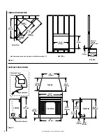
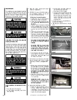
1. Complete the framing opening to the dimen-
sions specified in
Figure 2
.
2. Prepare the connections to power source:
120 Volt Connections - Locate the power
cord on the left side of the unit and connect
it to the outlet installed during the framing
(see
Figure 2)
.
Verify that the power to the
receptacle is off.
Hard wired installation:
Ensure that there is a minimum of 8" of the
service cable for connection to the junction
box on the fireplace.
- Loosen four screws to remove the junction
box cover plate.
- Disconnect and remove the 120 Volt power
cord from the fireplace wires.
- Position the fireplace into the framed-in
opening. Attach fireplace to frame using
nailing flanges provided.
- Complete the wiring to the fireplace as
shown on
Page 9
.
- Place all wire connectors inside the junction
box.
- Attach junction box cover plate with four
screws.
240 Volt Connections - Ensure that there
is a minimum of 8" of the service cable
for connection to the junction box on the
fireplace.
- Loosen four screws to remove the junction
box cover plate.
- Disconnect and remove the 120 Volt power
cord from the fireplace wires.
- Position the fireplace into the framed-in
opening. Attach fireplace to frame using
nailing flanges provided.
- Complete the wiring to the fireplace as
shown on
Page 10
.
- Place all wire connectors inside the junction
box.
- Attach junction box cover plate with four
screws.
The fireplace wires L1, L2, N, N1, N2 and
G are attached to the rear of the junction
box cable clamp for easy access.
Clearances
Sides
0 inches - 0 mm
Floor
0 inches - 0 mm
Top
0 inches - 0 mm
Table 2


