background image

42

Step 5. Adjust Charge to obtain the specified sub-cooling value. If the measured

sub-cool is below the listed requirement for the given outdoor and indoor
conditions, add charge. If the measured sub-cool is above the listed
requirement for the given outdoor and indoor conditions remove charge.

IMPORTANT: Excessive use of elbows in the refrigerant line set can produce
excessive pressure drop. Follow industry best practices for installation. Installation
and commissioning of this equipment is to be preformed by trained and qualified
HVAC professionals. For technical assistance contact your Distributor Service
Coordinator.

16.6 FINISHING UP INSTALLATION

• Disconnect pressure gauges from pressure ports; then replace the pressure port

caps and tighten adequately to seal caps. Do not over tighten.

• Replace the service valve caps finger-tight and then tighten with an open-end

wrench adequately to seal caps. Do not over tighten.

• Replace control box cover and service panel and install screws to secure service

panel. 

• Restore power to unit at disconnect if required.

• Configure indoor thermostat per the thermostat installation instructions and set

thermostat to desired mode and temperature.

17.0 ACCESSORIES

17.1 Remote Outdoor Temperature Kit (Part No. 47-102709-03)

This is a kit that has a longer remote sensor that can be installed away from the out-
door unit for better thermostat temperature display.

17.2 RXME-A02 Communicating 2 Wire Kit

This kit will allow the outdoor unit to communicate to the system with only 2 wires.

18.0 TROUBLESHOOTING

IMPORTANT: The JEC series units with the ICC (Integrated Compressor Control)
provide status and diagnostic information that greatly enhances the ability to quickly
diagnose system faults. Use the following troubleshooting guides as another tool in
system diagnostics.

!

NOTICE

Systems should not be fine tune charged below 40°F outdoor dry bulb.
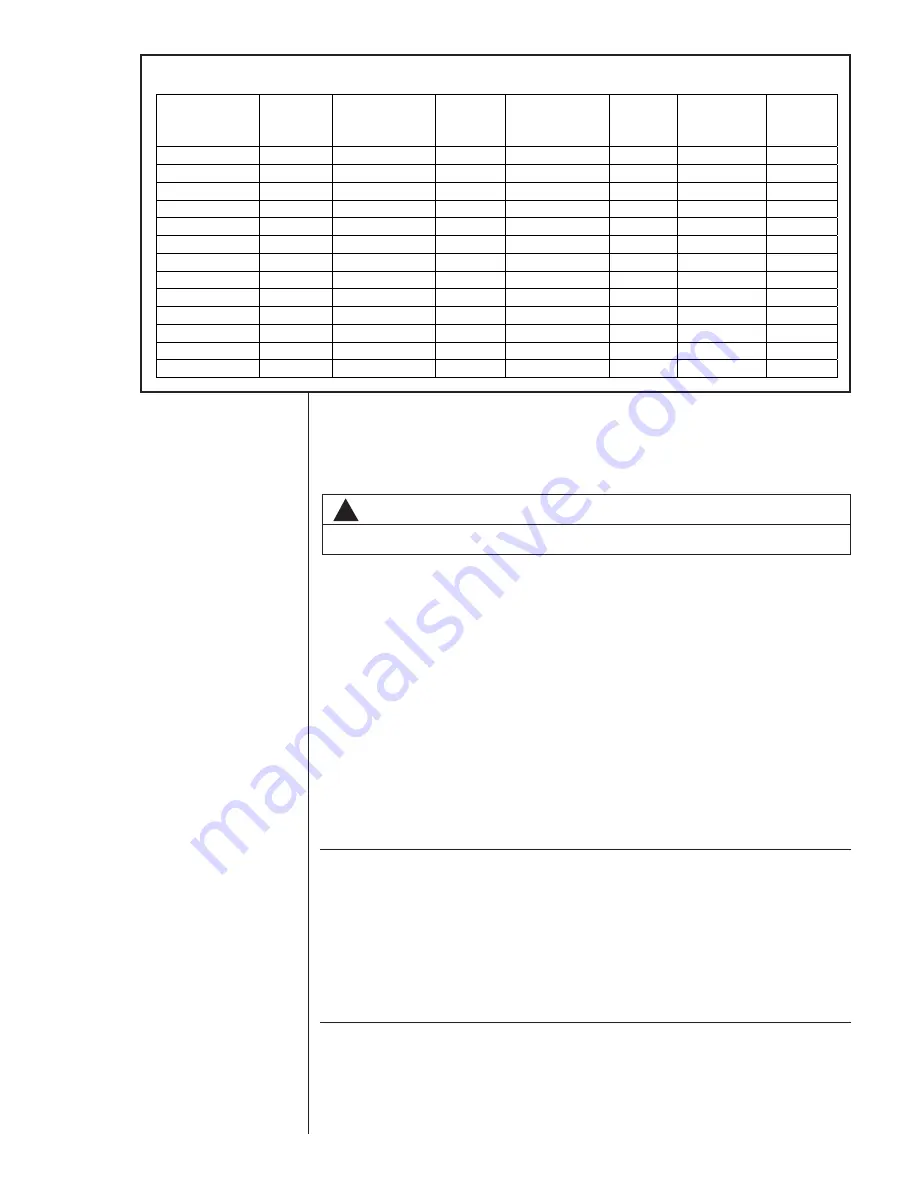


SATURATION 

TEMP 

(Deg. F) 

R-410A 

PSIG 

SATURATION 

TEMP 

(Deg. F) 

R-410A 

PSIG 

SATURATION 

TEMP 

(Deg. F) 

R-410A 

PSIG 

SATURATION 

TEMP 

(Deg. F) 

R-410A 

PSIG 

-150 

-30 

17.9 35 

107.5 

100 

317.4 

-140 

-25 

22 

40 

118.5 

105 

340.6 

-130 

-20 

26.4 45 

130.2 

110 

365.1 

-120 

-15 

31.3 50 

142.7 

115 

390.9 

-110 

-10 

36.5 55 

156.0 

120 

418.0 

-100 

-5 

42.2 60 

170.1 

125 

446.5 

-90 

48.4 

65 

185.1 

130 

476.5 

-80 

55.1 

70 

201.0 

135 

508.0 

-70 

10 

62.4 

75 

217.8 

140 

541.2 

-60 

0.4 

15 

70.2 

80 

235.6 

145 

576.0 

-50 

5.1 

20 

78.5 

85 

254.5 

150 

612.8 

-40 

10.9 

25 

87.5 

90 

274.3 


-35 

14.2 

30 

97.2 

95 

295.3 


TABLE 7

Summary of Contents for -ASL-JEC 18 SEER

Page 1: ... MAY RESULT IN IMPROPER INSTALLATION ADJUSTMENT SERVICE OR MAINTENANCE POSSIBLY RESULTING IN FIRE ELECTRICAL SHOCK PROPERTY DAMAGE PERSONAL INJURY OR DEATH WARNING 92 101691 05 12 SUPERSEDES 92 101691 05 11 AIR COOLED CONDENSING UNITS ASL JEC 18 SEER EQUIPPED WITH THE COMFORT CONTROL2 SYSTEM AND FEATURING DUAL DRIVE COMPRESSORS IN SELECT MODELS INSTALLATION INSTRUCTIONS INDICATES METRIC CONVERSION...

Page 2: ...l2 Control Wiring 20 12 3 Comfort Control2 Diagnostic Codes in Dual Drive 20 12 4 Comfort Control2 ICC Control Operation 21 12 5 Active Compressor Protection Mode 22 12 6 Test and Fault Recall Modes 24 12 7 ICC Diagnostic Codes 26 12 8 Conventional 24VAC Thermostat Control Wiring 29 12 9 Typical Non Communicating Thermostat Wiring Diagrams 30 12 10 Diagnostic Codes in Dual Drive Condensing Units W...

Page 3: ...SSORIES OR DEVICES MAY ADVERSELY AFFECT THE OPERATION OF THE AIR CONDITIONER AND MAY ALSO ENDANGER LIFE AND PROPERTY THE MANUFACTURER DISCLAIMS ANY RESPONSIBILITY FOR SUCH LOSS OR INJURY RESULTING FROM THE USE OF SUCH UNAUTHORIZED COMPONENTS ACCESSORIES OR DEVICES WARNING DISCONNECT ALL POWER TO UNIT BEFORE STARTING MAINTENANCE FAILURE TO DO SO CAN CAUSE ELECTRICAL SHOCK RESULTING IN SEVERE PERSON...

Page 4: ... PRESSURES USE APPROPRIATE CARE WHEN USING THIS REFRIGER ANT FAILURE TO EXERCISE CARE MAY RESULT IN EQUIPMENT DAM AGE OR PERSONAL INJURY CAUTION THE COMPRESSOR HAS AN INTERNAL OVERLOAD PROTECTOR UNDER SOME CONDITIONS IT CAN TAKE UP TO 2 HOURS FOR THIS OVERLOAD TO RESET MAKE SURE OVERLOAD HAS HAD TIME TO RESET BEFORE CONDEMNING THE COMPRESSOR CAUTION Only use evaporators approved for use on R 410A ...

Page 5: ... heat gain calculation must be made A heat gain calculation begins by measuring all external surfaces and openings that gain heat from the surrounding air and quantifying that heat gain A heat gain calculation also calculates the extra heat load caused by sunlight and by humidity removal Air conditioning systems are sized on the cooling load calculation There are two capacities that enable the equ...

Page 6: ...ts Compressor Fan Motor Full Load Amperes FLA Minimum Circuit Ampacity Amperes Fuse or HACR Circuit Breaker Outdoor Coil Weight Minimum Amperes Maximum Amperes Face Area Sq Ft m2 No Rows CFM L s Refrig Per Circuit Oz g Net Lbs kg Shipping Lbs kg ELECTRICAL PHYSICAL Rated Load Amperes RLA Locked Rotor Amperes LRA Rev 4 20 2012 024JEC 1 60 208 230 10 3 10 3 52 0 5 14 14 20 20 20 20 15 8 1 47 1 2500 ...

Page 7: ... directly on the unit cabinet In coastal areas locate the unit on the side of the building away from the water front Shielding provided by a fence or shrubs may give some protection but cannot violate minimum airflow and service access clearances Elevating the unit off its slab or base enough to allow air circulation will help avoid holding water against the basepan Regular maintenance will reduce...

Page 8: ...Applications Clearances below 6 inches will reduce unit capacity and efficiency Do not reduce the 60 inch discharge or the 24 inch service clearances Multiple Unit Applications When multiple condenser grille sides are aligned a 6 inch per unit clearance is recommended for a total of 12 between two units Two combined clearances below 12 inches will reduce capacity and efficiency Do not reduce the 6...

Page 9: ...stalling Servicing R 410A Models Manifold Sets Up to 800 PSIG High side Up to 250 PSIG Low Side 550 PSIG Low Side Retard Manifold Hoses Service Pressure Rating of 800 PSIG Recovery Cylinders 400 PSIG Pressure Rating Dept of Transportation 4BA400 or BW400 9 CAUTION R 410A systems operate at higher pressures than R 22 systems Do not use R 22 service equipment or components on R 410A equipment FIGURE...

Page 10: ...ressure rating of 800 psig Recovery cylinders need to have a 400 psig service pressure rating DOT 4BA400 or DOT BW400 Combustibility At pressures above 1 atmosphere mixture of R 410A and air can become combustible R 410A and air should never be mixed in tanks or supply lines or be allowed to accumulate in storage tanks Leak checking should never be done with a mixture of R 410A and air Leak checki...

Page 11: ...oil furnace Provide a service inlet to the coil for inspection and cleaning Keep the coil pitched toward the drain connection 7 0 INTERCONNECTING TUBING 7 1 Vapor and Liquid Lines Keep all lines sealed until connection is made Make connections at the indoor coil first Refer to Line Size Information in Tables 3 and 4 for correct size and multipliers to be used to determine capacity for various vapo...

Page 12: ...ndard on R 410A units Do not allow the vapor line and liquid line to be in contact with each other This causes an undesirable heat transfer resulting in capacity loss and increased power consumption The vapor line must be insulated If tubing has been cut make sure ends are deburred while holding in a position to prevent chips from falling into tubing Burrs such as those caused by tubing cutters ca...

Page 13: ...em Capacity Model Line Size Connection Size Inch I D mm Line Size Inch O D mm Liquid Line Size Outdoor Unit Below Indoor Coil Cooling Only Does not apply to Heat Pumps Total Equivalent Length Feet m 25 7 62 50 15 24 75 22 86 100 30 48 125 45 72 150 45 72 Maximum Vertical Separation Feet m 25 3 8 9 53 1 4 6 35 25 7 93 13 3 96 N A N A N A N A 5 16 7 93 25 10 97 32 9 75 29 8 84 26 7 93 23 7 01 20 6 1...

Page 14: ...n Size Inch I D mm Line Size Inch O D mm Suction Line Size Outdoor Unit BELOW Indoor Coil Cooling Only Does not apply to Heat Pumps Total Equivalent Length Feet m 25 7 62 50 15 24 75 22 86 100 30 48 125 45 72 150 45 72 25 3 4 19 05 5 8 15 88 Same as Liquid Line Size Table NA 3 4 19 05 NA 7 8 22 23 NA 37 3 4 19 05 5 8 15 88 Same as Liquid Line Size Table 3 4 19 05 Same as Liquid Line Size Table NA ...

Page 15: ...it are closed Clean the inside of the fittings and outside of the tubing with steel wool or sand cloth before soldering Always keep chips steel wool dirt etc out of the inside when cleaning Assemble tubing part way into fitting Apply flux all around the outside of the tubing and push tubing into stop This procedure will keep the flux from getting inside the system Remove the cap and schrader core ...

Page 16: ...ompressors are identified as Compressor A and Compressor B When facing the access panel Compressor A is on the left and Compressor B is on the right See Figure 3 8 2 Comfort Control2 System Control Identification The Dual Drive condensing units use one 1 serial communicating control per com pressor There is a label in the control box that identifies each control compressor combination When facing ...

Page 17: ... result in a noisy start up Crankcase Heater Operation Supplemental Crankcase heat is required to prevent refrigerant migration in sys tems with relatively high system refrigerant charges Each Dual Drive compressor has its own crankcase heater The crankcase heater control is integrated into the Comfort Control2 System and is designed for maximum energy savings Summary of operation The crankcase he...

Page 18: ...electrical arcing may result in a damaged or failed compressor Never run a scroll compressor while the system is in a vacuum or compressor failure will occur FINAL LEAK TESTING After the unit has been properly evacuated and service valves opened a halogen leak detector should be used to detect leaks in the system All piping within the heat pump evaporator and interconnecting tubing should be check...

Page 19: ... unit 24VAC transformer 40 VA minimum C 24VAC Common from the indoor unit 24VAC transformer 1 Data System Communications Line 1 2 Data System Communications Line 2 Low Volt Fuse If required replace with 3 A automotive ATC style blade fuse Low Pressure Control LPC Input Low pressure control is factory installed Low pressure control is an automatic resetting device High Pressure Control HPC Input Hi...

Page 20: ...run in conduit with the power supply Class I insu lation is required Class II insulation is required if run separate Low voltage wiring may be run through the insulated bushing provided in the 7 8 hole in the base panel up to and attached to the pigtails from the bottom of the control box Conduit can be run to the base panel if desired by removing the insulated bushing The serial communicating air...

Page 21: ...ays five 5 operational status codes 1 First Stage Cooling Operation When the ICC receives a command for first stage cooling operation a lower case c is displayed on the dual 7 segment LEDs Lower case c indicates first stage cooling operation 2 Second Stage Cooling Operation When the ICC receives a command for second stage cooling operation an upper case C is displayed on the dual 7 segment LEDs Up...

Page 22: ... modes 1 Low Pressure Control Lockout The ICC will display a flashing L followed by a flashing 21 when a low pressure control lockout occurs The ICC addresses low pressure control faults differently depending on the mode of unit operation cooling or heating mode Active Protection Code L21 Open low pressure control Cooling Mode If the LPC opens three 3 times during the same command for cooling oper...

Page 23: ...ng 06 when an open start circuit condition occurs Active Protection Code L6 Compressor open start circuit If the ICC lockouts L6 and L7 detect current in the run circuit without current pre sent in the start circuit the ICC will lockout the compressor to keep it from contin uing to operate and flash a L on the dual 7 segment LEDs followed by a 06 IMPORTANT This mode of active protection must be ma...

Page 24: ...1 A t to display momentarily on the dual 7 segment display Lower case t 2 The compressor will start and the outdoor fan will operate 3 The display will change to a steady c or C to show the current command for unit operation Note If a command for unit operation is present at the end of TEST mode will cause the unit to continue to operate If no command for unit operation is present TEST mode causes...

Page 25: ...nds with insulated probes and release The top and bottom segments of the dual 7 segment LEDs flash to indicate the history has been cleared Fault history is cleared with the top and bottom LED segments flash NOTE The memory card for the system has specific shared data for this system The memory card is attached to the control box with a tether The tether has an identification tag that can be used ...

Page 26: ...e Cause Troubleshooting Information FLASHING c FLASHING C t Test Mode The ICC is in TEST mode P Protector Trip A command for compressor operation is present but no current is measured to the compressor Motor protector open Line voltage disconnected 01 Long Run Time Compressor The compressor has continuously run for more than 18 hours in the cooling mode Low refrigerant charge Air ducts have substa...

Page 27: ... detects current in the Start circuit but not in the Run circuit of the compressor four 4 times in one compressor call 4 retries Check for damaged miswired or wrong run capacitor Check for broken wires loose connectors or miswired compressor Check compressor windings for continuity 07 Compressor Open Run Circuit The ICC detects current in the Start circuit but not in the Run circuit of the compres...

Page 28: ...r Ambient Temperature Fault The sensor detects an abnormally low or high outdoor ambient temperature Check unit placement If the outdoor unit is in a high temperature area wait until the ambient temperature drops and check sensor reading Replace the sensor Check sensor is installed correctly on control 93 Internal Control Fault The control is not functioning properly Check control for proper syste...

Page 29: ...e insulated bushing provided in the 7 8 hole in the base panel up to and attached to the pigtails from the bottom of the control box Conduit can be run to the base panel if desired by removing the insulated bushing A thermostat and a 24 volt 40VA minimum transformer are required for the control circuit of the condensing unit The furnace or the air handler transformer may be used if sufficient See ...

Page 30: ...Thermostat ASL Condensing Unit Y2 C R Y2 Field Installed Line Voltage WIRING INFORMATION Factory Standard ODD R Y1 Y2 G W2 R Y1 C L Y Y BL R BR W R DHM W1 W2 W1 C G HPN Air Handler Y1 Typical Two Stage Thermostat ASL Condensing Unit Y2 C R Y2 Field Installed Line Voltage WIRING INFORMATION Factory Standard ODD R Y1 Y2 G W2 R Y1 C L Y Y BL R BR W R DHM L W1 FIGURE 10 CONDENSING UNIT WITH ELECTRIC H...

Page 31: ...cond stage cooling or first stage second stage heating the red Y1 LED will illuminate The ICC has an on off fan delay of one 1 second for each stage of heating or cooling The ICC ignores the lower pressure control for the first 90 seconds of compressor operation On heat pumps the ICC ignores the LPC during the defrost cycle The dual 7 segment LED displays five 5 operational status codes 1 First St...

Page 32: ...ge drop 12 12 Active Compressor Protection Mode The ICC actively protects the compressor from harmful operation during a fault condition When the ICC detects a condition that could damage the compressor the ICC will enter active protection mode and lockout compressor operation The condition causing active protection must be resolved then the ICC can be reset to restart the system There are five 5 ...

Page 33: ...ICC will lockout the compressor to keep it from continuing to operate and flash a L on the dual 7 segment LEDs followed by a 04 IMPORTANT This mode of active protection must be manually reset 4 Open Start Circuit Lockout The ICC will display a flashing L followed by a flashing 06 when an open start circuit condition occurs Active Protection Code L6 Compressor open start circuit If the ICC lockouts...

Page 34: ...ressing the TEST button with an insulated probe for one 1 second and release The TEST mode causes the ICC to do the following 1 Resets the ICC from any active protection lockout mode 2 Resets the 3 minute anti short cycle timer 3 Energizes the unit without a call for unit operation If the 3 minute anti short cycle timer or 30 second minimum run timer is active a flashing c or C is displayed on the...

Page 35: ...ST and SW2 button for five 5 sec onds with insulated probes and release The top and bottom segments of the dual 7 segment LEDs flash to indicate the history has been cleared Fault history is cleared with the top and bottom LED segments flash 13 0 ELECTRICAL WIRING Field wiring must comply with the National Electric Code C E C in Canada and any applicable local code 13 1 Power Wiring It is importan...

Page 36: ...pend on the correct balance between indoor load and outdoor unit capacity Excessive indoor airflow increases the possibility of high humidity problems Low indoor airflow reduces total capacity and causes coil icing Serious harm can be done to the com pressor by low airflow such as that caused by refrigerant flooding Each ton of cool ing requires between 375 and 450 cubic feet of air per minute CFM...

Page 37: ...vacuating air and moisture from the system Air or nitrogen in the system causes high condensing temperatures and pressure resulting in increased power input and non verifiable performance Moisture chemically reacts with the refrigerant and oil to form corrosive hydrofluoric acid This attacks motor windings and parts causing breakdown After the system has been leak checked and proven sealed connect...

Page 38: ...esult in a damaged or failed compressor Never run a scroll compressor while the system is in a vacuum or compressor failure will occur 15 2 FINAL LEAK TESTING After the unit has been properly evacuated and service valves opened a halogen leak detector should be used to detect leaks in the system If a leak is detected the refrigerant should be recovered before repairing the leak The Clean Air Act p...

Page 39: ...p 2 Attach the low pressure hose to the common suction port connected to the common suction line between the reversing valve and compressor Step 3 Attach a temperature probe within 6 outside of the unit on the copper liquid line small line For more accurate measurements clean the copper line prior to measurement and use a calibrated clamp on temperature probe or an insulated surface thermocouple 3...

Page 40: ...t as necessary CHARGING BY LIQUID SUB COOLING MUST BE USED FOR FINAL CHARGE ADJUSTMENT With thermostat in the Off position turn the power on to the furnace or air handler and the heat pump Start the heat pump and the furnace or air handler with the thermostat Verify that the outdoor unit is operating in second stage and the indoor air mover is delivering the second stage airflow for the system siz...

Page 41: ...ice valve Use the pressure temperature chart below to note the corresponding saturation temperature for R410A at the measured liquid pressure Liquid Saturation Temperature SAT F _________ F Step 3 Note the liquid line temperature Liq __________ F as measured from a temperature probe located within 6 outside of the unit on the copper liquid line small line It is recommended to use a calibrated clam...

Page 42: ...installation instructions and set thermostat to desired mode and temperature 17 0 ACCESSORIES 17 1 Remote Outdoor Temperature Kit Part No 47 102709 03 This is a kit that has a longer remote sensor that can be installed away from the out door unit for better thermostat temperature display 17 2 RXME A02 Communicating 2 Wire Kit This kit will allow the outdoor unit to communicate to the system with o...

Page 43: ...y control in the outdoor units have a set of bias dipswitches set at a factory default to the ON position The sec ondary control dipswitches are defaulted off DO NOT CHANGE DIP SWITCHES Once the system is powered the airflow settings will be configured for all devices The outdoor unit will send information to configure indoor airflow If the indoor unit is incapable of supplying the required airflo...

Page 44: ...ared data is considered a back up for a lost or missing memory card Never remove the memory card from the unit or cut the tether of the memory card as it is the most effective way to transfer the shared data If the memory card is damaged or missing a new memory card can be ordered from Pro Stock The unit will operate without the memory card but a D4 error will be displayed on the seven segment dis...

Page 45: ...ault history and refer to Diagnostic Chart Note For solid comm LED check comm wiring term bus switches at ICC and AH ctrls Refer to panel cover documentation for Fault Code Troubleshooting Check fault history for other faults Check control voltage R and C to control Waiting for Anti S C Delay to clear Thermostat call For cooling no cooling No Yes Y1 LED lit No call received 24V Systems Check therm...

Page 46: ...low Recirculation of Inoperative Compressor Inoperative Indoor Blower Outdoor Air Valves Non condensibles Outdoor Check Valve Low on Charge Closed Higher than Ambient Restricted Indoor Air Entering Outdoor Coil Metering Device Restricted Indoor Wrong Outdoor Fan Rotation Metering Device Restriction in System Restricted Recirculation of Filter Drier Indoor Air Wrong Indoor Blower Rotation Inadequat...

Page 47: ...speed of blower or reduce restriction replace air filter High head low vapor pressures Restriction in liquid line expansion device or filter drier Remove or replace defective component Flowcheck piston size too small Change to correct size piston Incorrect capillary tubes Change coil assembly High head high or normal vapor Dirty outdoor coil Clean coil pressure Cooling mode Refrigerant overcharge ...

Page 48: ...nosis High voltage Power company problem Have problem corrected High head pressure Overcharge Check system charge Dirty heat pump coil Clean coil Faulty or wrong size Replace fan motor heat pump fan motor Faulty fan blade Replace fan blade or wrong rotation Replace with correct rotation motor Recirculation of air Correct installation Additional Heat Source Check for dryer vent near unit Check for ...

Page 49: ... High pressure switch Low pressure switch Ambient thermostat Solid state protection control or internal thermal sensors Compressor timed off on control or interlock No voltage on line side Blown fuses or tripped circuit breaker Check for short in wiring or unit of compressor contactor Improper wiring Re check wiring diagram Improper voltage High voltage Wrong unit Power supply problem Low voltage ...

Page 50: ...am out of calibration Customer misuse FLOODED STARTS SYMPTOMS POSSIBLE CAUSES CHECK OR REMEDIES Liquid in the compressor shell Faulty or missing crankcase heater Replace crankcase heater Too much liquid in system Incorrect piping Check Piping guidelines Overcharge Check and adjust charge SLUGGING SYMPTOMS POSSIBLE CAUSES CHECK OR REMEDIES On start up Incorrect piping Review pipe size guidelines TE...

Page 51: ...ble clockwise superheat settings Valve feeds too much refrigerant Moisture causing valve to stick open Recover refrigerant replace filter with low superheat and higher than drier evacuate system and then nor mal suction pressure recharge Dirt or foreign material causing Recover refrigerant replace filter valve to stick open drier evacuate system and recharge TEV seat leak A gurgling or hissing Rep...

Page 52: ...other refrigerant or refrigerant oil flowing position around the circumference of through suction line the suction line Unequal refrigerant flow through Ensure sensing bulb is located evaporator circuits properly Check for blocked distributor tubes Improper superheat adjustment Replace TEV or adjust superheat only possible with TEV having superheat adjustment Moisture freezing and partially Recove...

Page 53: ...ndercharge Low Low High Low Low Liquid Restriction Drier Low Low High High Low Low Evaporator Airflow Low Low Low Low Low Dirty Heat Pump High High Low Low High Low Outside Ambient Temperature Low Low High High Low Inefficient Compressor Low High High High Low TXV Feeler Bulb Charge Lost Low Low High High Low Poorly Insulated Sensing Bulb High High Low Low High SYSTEM PROBLEM INDICATORS TABLE 8 TE...

Page 54: ...54 FIGURE 12 WIRING DIAGRAM FOR ASL 024JEC 025JEC 036JEC 03JEC 19 0 WIRING DIAGRAMS ...

Page 55: ...55 FIGURE 13 WIRING DIAGRAM FOR ASL 039JEC 048JEC 060JEC DUAL DRIVE ...

Page 56: ...56 CM 0413 ...

Reviews: