4
Installation
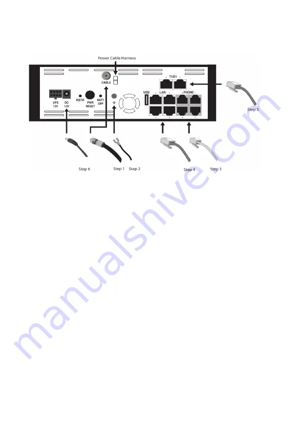
1. Connect the active RF coaxial cable to the “CABLE” connector.
2. Coaxial cable screen shield needs to be connected to the earth at the
building entrance per ANSI/NFPA 70, the National Electrical Code (NEC), in
particular Section 820.93, Grounding of Outer Conductive Shield of a Coaxial
Cable or in accordance with local regulation. For additional grounding, it is
strongly recommended that a grounding cable to be connected to the ground
screw terminal as shown in the diagram.
3. Connect any standard analog telephone or fax machine to ESBCs “PHONE”
connector, labeled 1-4.
4. Optionally, connect LAN port 2, 3, or 4 to corporate LAN which has IP Phone
or IP PBX.
5. Optionally, connect T1/E1 port 1 and Port 2 to a corporate TDM PBX. If only 1 T1/E1
connection is used to connect to a TDM PBX, connect to the ESBC T1/E1 Port 1 only.
Do not connect to T1/E1 Port 2 unless T1/E1 Port 1 is also connected to the same
TDM PBX. For wiring information, see T1/E1 cable wiring pin-out in Appendix B.
6. Connect included AC power cable to the electrical outlet and its cable to the
ESBC’s “12V DC” connector.
7. Secure AC power cord in the plastic cable harness for power cable in the back
of the unit.


