Book 43212455 (11/03)
16
SECTION 5 - INSTALLATION
Location
After the type of drive is determined, satisfactory installation depends upon the ability of the installer.
Refer to the appropriate foundation plan for the dimensions of the compressor package and the
appropriate separator foundation plan for the dimensions of the combination primary oil separator tank-
air receiver and the secondary separator tank (hereafter called the receiver separator).
Choose a clean, relatively cool location for the compressor package, and provide ample space around the
unit for general accessibility and to ensure effective heat dissipation. Extreme care must be taken in
locating an air-cooled unit of this type so there is an unrestricted supply of air to the cooling fan, which
pulls air over the oil cooler core. The fan discharge air must flow away from the unit so that it may be
readily dissipated to atmosphere without recirculating hot air to the fan intake. Any recirculation of the
cooling air may result in an excessively high compressor operating temperature. The compressor
package must be located so the compressor discharge temperature gauge and the air cleaner service
indicator will be fully visible. Included with the compressor package is a compressor discharge pressure
gauge and a discharge temperature gauge.
For the installation of the receiver separator, choose a location that is on the same level as or lower than
the compressor package. Ample space must be provided around the receiver to ensure the proper
installation of all piping connections. In addition, the receiver separator must be located so that the
separator element may be removed for inspection and service. Refer to the appropriate separator
foundation plan.
A condensate drain valve is factory supplied with the receiver separator. When installing the receiver
separator, provision should be made for easy access to this drain valve as it will be necessary to drain the
condensate daily before starting the unit.
NOTE
The condensate drain valve and line must
be located as the lowest point in the
lubricating and cooling oil system for proper
condensate removal.
The valve may also be used as a service valve for draining the lubricating and cooling oil at periodic
change intervals.
Exact level is not absolutely necessary, but it is recommended the unit be leveled with a sight glass or a
carpenter’s level set on the compressor housing. Leveling may be accomplished by shimming the unit
near the unit’s bolting holes. Be sure to use steel shims. Mounting holes are provided on the bottom of
the base and weld nuts are provided on the sides of the frame. Either may be used for mounting.
Inlet Piping
Each unit is supplied with standard air cleaners to protect the compressor from normal air-borne dust and
dirt. If necessary, the air cleaners may be removed and remotely mounted for ease in accessibility.
Summary of Contents for HP600CMH
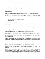
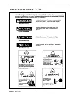
Page 8: ...Book 43212455 11 03 8 IMPORTANT SAFETY INSTRUCTIONS ...
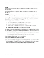
Page 9: ...Book 43212455 11 03 9 ...
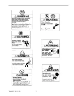
Page 10: ...Book 43212455 11 03 10 ...
Page 14: ...Book 43212455 11 03 14 fold ...
Page 37: ...Book 43212455 11 03 37 ...
Page 44: ......

