background image

Maintenance

RT-SVX51B-EN

31 

Due to the soft material and thin walls of the MCHE coils, 
the traditional field maintenance method recommended 
for Round Tube Plate Fin (RTPF) coils does not apply to 
microchannel coils.

Moreover, chemical cleaners are a risk factor to MCHE due 
to the material of the coil. The manufacturer does not 
recommend the use of chemical cleaners to clean 
microchannel coils. Using chemical cleaners could lead to 
warranty claims being further evaluated for validity and 
failure analysis.

The recommended cleaning method for microchannel 
condenser coils is pressurized water or air with a non-
pinpoint nozzle and an ECU of at least 180 with pressure no 
greater than 600 psi. To minimize the risk of coil damage, 
approach the cleaning of the coil with the pressure washer 
aimed perpendicular to the face of the coil during cleaning. 
Optimum clearance between the sprayer nozzle and the 
microchannel coil is 1”–3”.

Final Process

For future reference, you may find it helpful to record the 
unit data requested below in the blanks provided.

(1) Complete Unit Model Number:

_____________________________________________________

(2) Unit Serial Number:

_____________________________________________________

(3) Wiring Diagram Numbers (from unit control panel)

— schematic(s)

_____________________________________________________
_____________________________________________________
— connection(s)

_____________________________________________________
____________________________________________________

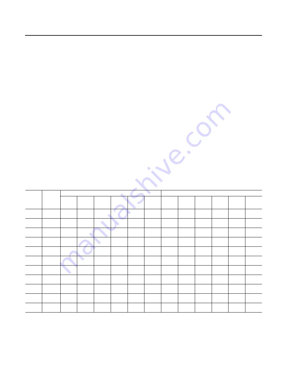
Table 10.

Sample maintenance log

Date 


Current 

Ambient 

Temp F/C 

Refrigerant Circuit #1

Refrigerant Circuit #2

Compr. 

Oil Level 

Suct. 

Press. 

Psig/kPa 

Disch. 

Press 

Psig/kPa 

Liquid 

Press 

Psig/kPa 

Super- 

heat F/C

 Sub-cool 

F/C 

Compr. 

Oil Level 

Suct. 

Press. 

Psig/kPa 

Disch. 

Press 

Psig/kPa 

Liquid 

Press 

Psig/kPa 

Super- 

heat F/C

Sub-cool 

F/C 

- ok

- low

- ok

- low

- ok

- low

- ok

- low

- ok

- low

- ok

- low

- ok

- low

- ok

- low

- ok 

- low

- ok 

- low

- ok

- low

- ok

- low

- ok

- low

- ok

- low

- ok

- low

- ok

- low

- ok

- low

- ok

- low

- ok

- low

- ok

- low

- ok

- low

- ok

- low

Summary of Contents for GAC180-300

Page 1: ...ing Improperly installed adjusted or altered equipment by an unqualified person could result in death or serious injury When working on the equipment observe all precautions in the literature and on the tags stickers and labels that are attached to the equipment Packaged Rooftop Air Conditioners Foundation Gas Electric 15 25 Tons 60Hz Installation Operation and Maintenance Model Numbers GAC180 300...

Page 2: ...dicates a potentially hazardous situation which if not avoided could result in minor or moderate injury It could also be used to alert against unsafe practices NOTICE Indicates a situation that could result in equipment or property damage only accidents WARNING Proper Field Wiring and Grounding Required Failure to follow code could result in death or serious injury All field wiring MUST be perform...

Page 3: ...in whole or in part without written permission Trane reserves the right to revise this publication at any time and to make changes to its content without obligation to notify any person of such revision or change Trademarks All trademarks referenced in this document are the trademarks of their respective owners Revision Summary RT SVX51B EN 30 Dec 2014 Updated Warranty section WARNING Proper Field...

Page 4: ...FIYUDC 24 Through the Base Gas Utility Option 25 Pre Start 26 Verifying Proper Air Flow Units with Belt Drive Indoor Fan 26 Electromechanical Controls Test Procedure 26 Start Up 27 Standard Economizer Start Up 27 LLE Controls Test Procedure 27 Compressor Start Up 27 Heating Start Up 28 Final System Set Up 28 Maintenance 29 Fan Belt Adjustment Belt Drive Units 29 Monthly Maintenance 30 Final Proces...

Page 5: ...1 5 G A C 1 8 0 A 3 E H A 0 0 1 2 3 4 5 6 7 8 9 10 11 12 13 J Low Leak Economizer Dry Bulb w o Barometric Relief5 L Low Leak Economizer Reference Enthalpy w o Barometric Relief5 N Low Leak Economizer Comparative Enthalpy w o Barometric Relief5 Digit 15 Supply Fan Drive Type Motor 0 Standard Motor 1 Oversized Motor 7 Multi Speed Standard Motor 9 Multi Speed Oversized Motor Digit 17 Condenser Coil P...

Page 6: ... temporary heat is provided in the building Isolate all side panel service entrances and base pan openings e g conduit holes S A and R A openings and flue openings from the ambient air until the unit is ready for start up Note Do not use the unit s heater for temporary heat without first completing the start up procedure detailed under Start Up p 27 The manufacturer will not assume any responsibil...

Page 7: ...ted whenever the position of the economizer dampers meets or exceed the power exhaust setpoint when the indoor fan is on The setpoint panel is located in the return air section and is factory set at 25 50 for LLE To configure the LLE controller set EXH1 SET or EXH1 L EXH1 H with two speed fan in the SETPOINTS menu 2 speed fan mode requires AUX2 I set as W Evaporator Frost Control Optional This inp...

Page 8: ...pied status is to use the G input fan is running Connect the G input to the OCC SENSOR wire at customer connections The controller will then operate in the occupied mode every time the indoor fan is running Initiation of Operating Modes JADE Controller The JADE controller is able to initiate the following modes Compressor Economizer Fans Heating System and Cooling System The Compressor mode is ini...

Page 9: ...inimum distances necessary to assure adequate serviceability cataloged unit capacity and peak operating efficiency Providing less than the recommended clearances may result in condenser coil starvation short circuiting of exhaust and economizer airflows or recirculation of hot condenser air Figure 1 Typical installation clearance for single and multiple unit applications 5 8 5 0 ...

Page 10: ...Dimensional Data 10 RT SVX51B EN Figure 2 Gas electric units overview Figure 3 Gas electric units front side views 15 25 tons standard efficiency ...

Page 11: ...Dimensional Data RT SVX51B EN 11 Figure 4 Gas electric units plan view 15 25 tons standard efficiency 82 1 4 Figure 5 Foundation units back view horizontal configuration 15 25 tons standard efficiency ...

Page 12: ...andard efficiency Figure 7 Downflow duct connections field fabricated 15 25 tons standard efficiency 9 1 25 4 MM CURB FLANGE LONG SIDES SHORT SIDES Notes Duct flanges mount 7 7 16 down inside the curb on the 1 1 curb flanges Roofcurb is intended for downflow use only ...

Page 13: ...ure 8 Downflow unit clearance 15 25 tons standard efficiency Figure 9 Barometric relief and economizer 15 25 tons standard efficiency MOTORIZED DAMPER BAROMETRIC RELIEF IS FOR USE WITH A DOWNFLOW ECONOMIZER ONLY FOR LOW LEAK FOR LOW LEAK ...

Page 14: ...Dimensional Data 14 RT SVX51B EN Figure 10 Manual damper 15 25 tons standard efficiency ...

Page 15: ... 475 391 451 54 37 25 GAC300A 2327 2058 723 493 380 455 53 35 a Weights are approximate Horizontal and downflow unit and corner weights may vary slightly b Weights do not include additional factory or field installed options accessories c Corner weights are given for information only 15 25 ton models must be supported continuously by a curb or equivalent frame support Figure 11 Corner weights WARN...

Page 16: ...plied by others gaskets must be installed around the curb perimeter flange and the supply and return air opening flanges General Unit Requirements The checklist listed below is a summary of the steps required to successfully install a commercial unit This checklist is intended to acquaint the installing personnel with what is required in the installation process It does not replace the detailed in...

Page 17: ...ard or low leak economizer Installation Instructions for proper position and setup Install all access panels Controller Wiring Schematic LLE For additional information go to the Installation Instructions ACC SVN178 EN Main Electrical Power Requirements Verify that the power supply complies with the unit nameplate specifications Inspect all control panel components tighten any loose connections Con...

Page 18: ...onfiguration the factory installed limit control TCO1 must be replaced with the TCO1 for horizontal applications shipped in the heater compartment Replace TCO1 following instructions below 1 Remove the heat section access panel 2 Remove TCO1 from shipping location attached to the gas manifold vertical leg as shown below 3 Replace and discard the existing TCO1 originally installed at the factory fo...

Page 19: ... only copper conductors to connect the power supply to the unit Note If the unit is not equipped with an optional factory installed nonfused disconnect switch or circuit breaker a field supplied disconnect switch must be installed at or near the unit in accordance with the National Electrical Code NEC latest edition Main Unit Power Standard Wiring The electrical service must be protected from over...

Page 20: ...installing any connecting wiring refer to Unit Dimensions p 12 for the electrical access locations provided on the unit and Table 2 p 20 for AC conductor sizing guidelines 1 Use copper conductors unless otherwise specified 2 Ensure that the AC control wiring between the controls and the unit s termination point does not exceed three 3 ohms conductor for the length of the run Note Resistance in exc...

Page 21: ...lve Never adjust the staged gas pressure valve to a negative pressure 3 5 3 5 3 5 3 5 Combustion Blower Suction Pressure 1st Stage 0 6 to 0 8 0 6 to 0 8 0 6 to 0 8 0 6 to 0 8 Combustion Blower Suction Pressure 2nd Stage 1 to 1 3 1 to 1 3 1 to 1 3 1 to 1 3 Minimum Flame Sensing Current b b A voltage reading across pens V V is equatable to the flame sensing current One volt equals one micro amp 5 0 ...

Page 22: ...it protection switch and remove the phase sequence indicator Compressor Crankcase Heaters Each compressor can be equipped with a crankcase heater The proper operation of the crankcase heater is important to maintain an elevated compressor oil temperature during the Off cycle to reduce oil foaming during compressor starts Oil foaming occurs when refrigerant condenses in the compressor and mixes wit...

Page 23: ... bearings for sufficient lubrication If the belts require adjustment or if the bearings need lubricating refer to the maintenance section of this manual for instructions Verify that a condensate trap is installed and the piping is properly sized and pitched Verify that the correct size and number of filters are in place Inspect the interior of the unit for tools and debris and install all panels i...

Page 24: ...ty found on the unit nameplate and the N E C 4 Route low voltage class II control wiring through hole in base of unit but not through high voltage conduit Feedcontrolwiringthroughbushingprovided on side panel Route wires through loose wire ties provided 5 Tighten the wire ties Secure the excess wire bundle under the wire ties in the outdoor section Do not leave excess wire in the electrical enclos...

Page 25: ... power including remote disconnects and discharge all motor start run capacitors before servicing Follow proper lockout tagout procedures to ensure the power cannot be inadvertently energized Verify with an appropriate voltmeter that all capacitors have discharged Failure to disconnect power and discharge capacitors before servicing could result in death or serious injury For additional informatio...

Page 26: ...0 using the setpoint potentiometer located on the Economizer Control ECA if applicable Electromechanical Controls Test Procedure See unit schematic for correct wire numbers Fan Test and Minimum Ventilation Connect red thermostat wire R to black thermostat wire G Economizer Cooling Connect a jumper wire across OAT on Economizer Control ECA Connect red thermostat R wire to yellow thermostat wire Y1 ...

Page 27: ... after powered If OA sensor or Sylk Bus device sensor or actuator is disconnected during the set up mode the JADE will not alarm that failure The MA sensor is a system critical sensor if the MA sensor is removed during the set up mode the JADE will alarm After 60 minutes the JADE controller will change to operation mode and all components removed or failed will alarm in the operation mode Upon pow...

Page 28: ...hecked open the main power disconnect switch to reset the unit Final System Set Up After completing all of the pre start and start up procedures outlined in the previous sections i e operating the unit in each of its modes through all available stages of cooling and heating perform these final checks before leaving the unit Program the Night Setback NSB panel if applicable for proper unoccupied op...

Page 29: ...is number represents the force in pounds required to give the needed deflection 6 Compare the force scale reading Step 5 with the appropriate force value listed in Table 9 p 29 If the force reading is outside the range readjust the belt tension Note Actual belt deflection force must not exceed the maximum force value shown in Table 9 p 29 7 Recheck the belt tension at least twice during the first ...

Page 30: ...s data on an operator s maintenance log like the one shown in Table 10 p 31 If the operating pressures indicate a refrigerant shortage measure the system superheat For guidelines refer to Compressor Start Up p 27 Note Do NOT release refrigerant to the atmosphere If adding or removing refrigerant is required the service technician must comply with all federal state and local laws Heating Season Ins...

Page 31: ...ozzle and the microchannel coil is 1 3 Final Process For future reference you may find it helpful to record the unit data requested below in the blanks provided 1 Complete Unit Model Number _____________________________________________________ 2 Unit Serial Number _____________________________________________________ 3 Wiring Diagram Numbers from unit control panel schematic s ____________________...

Page 32: ... Flashes System Lockout 3 Flashes Pressure Switch Fail 4 Flashes TC01 or TC02 Open 5 Flashes Flame w o Gas Valve 6 Flashes Flame Rollout Open Cooling Failure 1 Cooling and heating set point slide pot on the thermostat has failed 2 CC1 or CC2 24 VAC control circuit has opened Check CC1 CC2 coils and any of the controls below that apply to the unit HPC1 HPC2 LPC1 LPC2 DLT1 DLT2 Frostat Simultaneous ...

Page 33: ...ure Status Diagnostics by the methods previously explained Diagnostics will be lost when the power to the unit is disconnected Method 1 To reset the system from the space turn the Mode selection switch at the thermostat to the Off position After approximately 30 seconds turn the Mode selection switch to the desired mode i e Heat Cool or Auto Method 2 To reset the system at the unit cycle the unit ...

Page 34: ...D180 300 60Hz 2 Stage Gas Heat Raceway Connection 208 575 2313 2241 GAC180 300 GAD180 300 60Hz 2 Stage Gas Heat Control Box Connection 208 230 2313 2232 GAC180 300 GAD180 300 60Hz 2 Stage Gas Heat 460 575 2313 2236 GAC180 300 GAD180 300 60Hz 2 Stage Gas Heat Multi Speed Fans Power 208 230 2313 2226 GAC180 300 GAD180 300 60Hz 2 Stage Gas Heat w VFD 460 575 2313 2228 GAC180 300 GAD180 300 60Hz 2 Sta...

Page 35: ... so the above limitation or exclusion may not apply to you This warranty gives you specific legal rights and you may also have other rights which vary from state to state Trane 2701 Wilma Rudolph Blvd Clarksville TN 37040 1008 Attention Manager Product Service GW 602 4800 This warranty is for commercial usage of said equipment and not applicable when the equipment is used for a residential applica...

Page 36: ...014 Supersedes RT SVX51B EN Oct 2014 The warranty and liability set forth herein are in lieu of all other warranties and liabilities whether in contract or in negligence express or implied in law or in fact including implied warranties of merchantability and fitness for particular use In no event shall the Company be liable for any incidental or consequential damages Trane 2701 Wilma Rudolph Blvd ...

Reviews: