Ingersoll-Rand EP 20-ESP Operators/Instruction Manual And Parts List Download Page 27

25

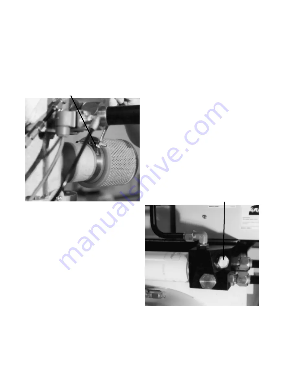
4.9 INLET AIR FILTER ELEMENT

The inlet air filter should be changed at the interval
shown in the maintenance chart or any time the filter
becomes dirty.

The filter element is not washable and must be
replaced. Remove the filter by loosening the clamp on
the filter assembly located on the Inlet Control Valve.
Remove and discard the old filter element. Install a
new filter element. Tighten clamp (See Figure 4.9-1).

FIGURE 4.9-1 INLET AIR FILTER 

4.10 COOLANT FILTER

Time of change - after the first 150 hours and every
1000 hours thereafter, or when the coolant is being
changed. In dirty operating environments, the filter
should be changed more frequently.

Before beginning any work on the compressor, open,
lock and tag the main electrical disconnect and close
the isolation valve on the compressor discharge. Wait
2 minutes after stopping to allow internal pressure to
dissipate. Vent residual pressure from the unit by slow-
ly unscrewing the coolant fill plug one turn.
Unscrewing the fill plug opens a vent hole, drilled in
the plug, allowing the pressure to release to atmos-
phere (See Figure 4.3-1). A slight mist or oil droplets
may be visible during venting. Do not remove fill plug
until all pressure has vented from the unit. Also vent
piping by slightly opening the drip leg valve . When
opening the drain valve or removing the coolant fill
plug, stand clear of the valve discharge, wear work
gloves and appropriate eye protection.

SPECIAL TOOLS

Suitable clean drain pan or container to hold coolant
drained from unit.

A quantity of proper coolant sufficient to top off the
coolant level in the compressor.

One genuine IR replacement coolant filter of the prop-
er type for the unit.

1. Place a clean pan under the coolant filter.

2. Using a filter wrench, remove the coolant filter.
Remember that the filter and coolant may be hot!

3. Discard the old filter.

4. Wipe the sealing surface of the filter head with a
clean lint-free rag to prevent entry of dirt into the sys-
tem.

5. Remove the replacement filter from its protective
package.

6. Apply a small amount of clean coolant on the rubber
seal of the filter.

7. Screw filter on until the seal makes contact with the
seat on the filter header. Tighten approximately one
half to three quarters turn additional.

8. Remove coolant fill plug (See Figure 4.10-1).

FIGURE 4.10-1 FILL PLUG

CLAMP

FILL PLUG

Summary of Contents for EP 20-ESP

Page 1: ...tain a clear knowledge of the unit and of the duties to be performed while operating and maintaining the unit RETAIN THIS MANUAL WITH UNIT This Technical manual contains IMPORTANT SAFETY DATA and shou...

Page 2: ...WARRANTIES OF MERCHANTABILI TY AND FITNESS FOR A PARTICULAR PURPOSE ARE HEREBY DISCLAIMED Correction by the Company of nonconformities whether patent or latent in the manner and for the period of tim...

Page 3: ...o make such changes or add such improvements to products sold previously No of units on order Customer Order No Ingersoll Rand Co Order No For ready reference Record the serial number and model number...

Page 4: ...ge check valve screen orifice 4 15 cooler cores 4 16 motor greasing 5 0 TROUBLE SHOOTING 6 0 REFERENCE DRAWINGS 6 1 electrical schematic full voltage 6 2 electrical schematic star delta 6 3 piping dia...

Page 5: ...sor has high and danger ous voltage in the motor starter and con trol box All installations must be in accor dance with recognized electrical codes Before working on the electrical system be sure to r...

Page 6: ...ENT FOR BREATHING AIR AND OR AQUA LUNG SERVICE If the model number on this air compressor contains letters BAP the compressor is suitable for use in breathIng air services In the absence of such a des...

Page 7: ...IEW RIGHT SIDE VIEW NOTICE Rotation INGERSOLLrAND WARNING Hot surface Can cause severe injury Do not touch Allow to cool before servicing INGERSOLLrAND 39541362 39861810 39544150 CAUTION Incorrect lif...

Page 8: ...e instructions in the Operators Instruction Manual Before Starting 1 Check Coolant level and add coolant if necessary 2 Verify that main isolation valve is open 3 Close main disconnect switch Starting...

Page 9: ...Cap Use only recommended coolant Read instruction book before servicing 39540281 39540257 39540240 39541362 39540166 CAUTION Use of incorrect coolant can cause system contamination Use only ROTALUBETM...

Page 10: ...of the compressor 2 2 FOUNDATION REQUIREMENTS The compressor can be installed on any level floor that is capable of supporting the weight When sound transmission is of particular importance it is oft...

Page 11: ...n such as a fence or security system should be provided to prevent unauthorized access FIGURE 2 3 1 TYPICAL OUTDOOR SHELTERED INSTALLATION 35 F 2 C AND ABOVE DISCHARGE PIPE STEEL POWER DISCONNECT SWIT...

Page 12: ...the drain piping should include an open funnel or some type of sight flow indicator It is possible that additional condensation can occur if the downstream piping cools the air even further Therefore...

Page 13: ...ressor before the common receiver See Figure 2 4 3 To assure long trouble free operation of a compressor operating with On line Off line and Auto Stop Start control the system volume must be large eno...

Page 14: ...nel front 2 6 VOLTAGE CONVERSION IMPORTANT This procedure should only be carried out by a qualified electrician electrical contractor or your local Ingersoll Rand Distributor or Air Center NOTE This p...

Page 15: ...turn As the fill plug is unscrewed approximately one turn a small amount of pressure may be released Do not remove the fill plug until all pressure has been vented Once pressure is vented finish remo...

Page 16: ...ator element When the unit is operating the coolant is pressurized and forced to the compressor bearings The compressor is provid ed with a temperature switch which will shut the unit down in case of...

Page 17: ...adequate oil flow and proper coolant air separation The non return check valve prevents line pressure from exhausting back through the airend at shutdown and during periods of unloaded operation The...

Page 18: ...s to the reset point of 1PS about 12 psig 8 bar the unit should reload The pressure switch dif ferential is adjustable and factory set at about 12 psig 8 bar to meet the requirements of the average ap...

Page 19: ...ent screw B clockwise This will decrease the lower set ting only The higher setting will not change Similarly to decrease the differential turn the differential adjust ment screw B counterclockwise Th...

Page 20: ...0 X REPLACE ROTALUBE TM 1000 COOLANT 1000 X REPLACE ULTRA COOLANT OPTIONAL 8000 X REPLACE SHAFT SEAL 8000 X GREASE ODP MOTOR 2000 X GREASE TEFC MOTOR 1000 X TIME INTERVAL WHICHEVER COMES FIRST INITIAL...

Page 21: ...end of any non service period CAU TION High pressure air will discharge through the discharge ports of the valve during try lever test Wear ample clothing gloves safety glasses and ear protection dur...

Page 22: ...st be loosened for reposi tioning To reposition the motor sheave 1 Remove drive belts See Section 4 6 2 Remove the three hex head screws that hold motor sheave to sheave bushing See Figure 4 5 3 3 Lub...

Page 23: ...8024 Loctite 609 4 6 DRIVE BELTS Insure that the compressor is isolated from the compressor air system by closing the isolation valve and venting pressure from the drip leg Insure that the main power...

Page 24: ...inadvertent damage during installation Be sure all tools are free of contaminants before installation 13 Put a thin continuous coat of Loctite 609 on the outer diameter of the double lip seal 14 Remo...

Page 25: ...ttach the seal housing to the rotor housing with nine screws and tighten to 18 Ibs ft 2 5 kg m 31 Reinstall sheave and sheave retaining hardware apply Loctite 242 to clamp screw and tighten to 32 Ibs...

Page 26: ...lation Tool press the seal into the seal housing from the outboard side until the seal is flush with the surface of the seal housing Do not push the seal beyond the flush position The seal should be o...

Page 27: ...o atmos phere See Figure 4 3 1 A slight mist or oil droplets may be visible during venting Do not remove fill plug until all pressure has vented from the unit Also vent piping by slightly opening the...

Page 28: ...olant sufficient to refill the coolant level in the compressor One genuine IR replacement coolant filter of the prop er type for the unit The coolant should be drained soon after the com pressor has b...

Page 29: ...en lock and tag the main electrical disconnect and close the isolation valve on the compressor discharge Wait 2 minutes after stopping to allow internal pressure to dissipate Vent residual pres sure f...

Page 30: ...ing the pressure to release to atmosphere See Figure 4 3 1 A slight mist or oil droplets may be visible dur ing venting Do not remove fill plug until all pres sure has vented from the unit Also vent p...

Page 31: ...nt sealing o ring from the housing 7 Verify that the drain hole in the inlet control valve is clean See Figure 4 3 4 8 Install new element sealing o ring in housing Make sure o ring is properly seated...

Page 32: ...k valve screen orifice assembly to the tubing lines The fitting must be re installed with the screen on the upstream side of the orifice as indi cated by the flow arrow See Figure 4 15 1 FIGURE 4 14 1...

Page 33: ...cylinder showing cubic centimeters cc may be used or a 35mm film canister can give a close approximation for 2 cubic inches of volume when filled 3 Add the recommended volume of the recommended lubri...

Page 34: ...Voltage Variation 6 Compressor Operating Above Rated Pressure 7 Dirty Separator Filter Element 8 Low Voltage 9 Unbalanced Voltage 10 Dirty Air Filter 11 Compressor Operating Unloaded 12 High Voltage...

Page 35: ...33 6 0 REFERENCE DRAWINGS 6 1 ELECTRICAL SCHEMATIC FULL VOLTAGE 39884143 REV 01...

Page 36: ...34 6 2 ELECTRICAL SCHEMATIC STAR DELTA 39884150 REV 01...

Page 37: ...IPING LEGEND A AIR PIPING C COOLANT PIPING CA CONTROL AIR PIPING NOTES 1 FOR CUSTOMER CONNECTIONS SEE FOUNDATION PLAN OF UNIT 2 DASHED ITEMS ARE OPTIONAL 3 PRESSURE SWITCH PRESSURE GAUGE ARE CONNECTED...

Page 38: ...36 6 4 FOUNDATION PLAN TANK MOUNTED CONTINUED 39871975 REV 03...

Page 39: ...37 6 4 FOUNDATION PLAN TANK MOUNTED 39871975 REV 03...

Page 40: ...38 6 5 FOUNDATION PLAN BASE MOUNTED CONTINUED 39872835 REV 03...

Page 41: ...39 6 5 FOUNDATION PLAN BASE MOUNTED 39872835 REV 03...

Page 42: ...all Type Valve UNION Aids in Disconnecting Compressor From The System PRESSURE GAUGE DRIP LEG MANOMETER DIFFERENTIAL PRESSURE INDICATOR THERMOMETER I R AUTOMATIC DRAIN VALVE FALSE LOADER Blows Off Air...

Page 43: ...with a description of NSS are not sold separately and must be purchased as an assembly Items with a description of Ref indicate that the item is located elsewhere in the parts list HOW TO USE THIS PAR...

Page 44: ...42 39876461 REV 02...

Page 45: ...939 1 LUG GROUND 4 39403290 1 RELAY CONTROL 1CR 5 39125091 1 SOCKET CONTROL RELAY 6 35258508 1 RELAY AUTO RESTART TIME DELAY 7 35245224 1 SOCKET TIMER RELAY 8 39242268 1 LIGHT AMBER INDICATOR AUTO RES...

Page 46: ...44 39880844 REV 01...

Page 47: ...39975 1 BLOCK TERMINAL 5 39190939 1 LUG GROUND 6 39403290 1 RELAY CONTROL 1CR 7 39125091 2 SOCKET CONTROL RELAY 8 35258508 1 RELAY AUTO RESTART TIME DELAY 1TD 9 35245224 1 SOCKET TIMER RELAY 10 352497...

Page 48: ...46 39872031 REV 01 SEE PIPING ASSEMBLY OPTIONS...

Page 49: ...1 1 TUBE OIL COOLER SEPARATOR TUBE Ref Part No Number Qty Description 23 39881974 1 DEFECTOR AIR 23A 39133145 4 SCREW 24 39878913 1 FAN 50 60HZ 24A 96705082 4 SCREW 25 39872049 1 RING FAN INLET 25A 39...

Page 50: ...01 NEMA 1 NEMA 4 TO RECEIVER TANK OR ELBOW IN ICV DISCHARGE BASE MOUNTED UNITS TO RECEIVER TANK OR ELBOW IN ICV DISCHARGE BASE MOUNTED UNITS TO HIGH AIR TEMPERATURE SWITCH AIREND TO HIGH AIR TEMPERATU...

Page 51: ...Ref Part No Number Qty Description 1 xxxxxxxx 1 ASSEMBLY STARTERBOX 2 95333266 1 CONNECTOR CONDUIT 2A 39135355 1 LOCKNUT CONDUIT SEAL 3 39132303 30 CONDUIT 4 95333373 1 ELBOW CONDUIT 4A 39135355 1 LOC...

Page 52: ...50 39872023 REV 02 TO AFTERCOOLER TO AFTERCOOLER...

Page 53: ...UPLING 33 39114079 1 LOCKNUT NEMA 1 39108949 1 LOCKNUT NEMA 4 34 39416128 1 SWITCH HIGH AIR TEMPERATURE 35 39404165 1 O RING 36 39848148 1 TUBE FRONT BEARING FEED 20 25 HP Piping Ref Part No Number Qt...

Page 54: ...E Tubing No Thread Size Size 39404157 7 16 20 1 4 39404132 9 16 18 3 8 39404165 3 4 16 1 2 39437074 7 8 14 5 8 39407531 1 1 16 12 3 4 39404173 1 5 16 12 1 39404140 1 5 8 12 1 1 4 39406996 1 7 8 12 1 1...

Page 55: ...NE PRESSURE NEMA 4 39201884 1 CONTACT AUXILIARY 1Ma 2Ma FOR SIZE F K CONTACTORS 39240064 1 CONTACT AUXILIARY 1Ma 2Ma FOR SIZE N CONTACTOR 39245337 1 HOURMETER 60 HZ 39226618 1 HOURMETER 50 HZ 39233382...

Page 56: ...AD SIZE N 39237367 1 STAR DELTA STARTER PARTS SIZE F CONTACTOR STARTER 1M SIZE F 39239850 1 CONTACTOR STARTER REVERSING 1S 2M 39239868 1 KIT STARTER CONTACT SIZE F 1 COIL STARTER SIZE F 39226592 1 REL...

Page 57: ...55 DATE RUN TIME WORK DONE QTY UNIT WORK HOURS MEASURE BY 8 0 MAINTENANCE RECORD...

Page 58: ...56 DATE RUN TIME WORK DONE QTY UNIT WORK HOURS MEASURE BY MAINTENANCE RECORD...

Reviews: