


19
Before beginning any work on the compressor,
open, lock and tag the main electrical disconnect
and close the isolation valve on the compressor
discharge. Wait 2 minutes after stopping to allow
internal pressure to dissipate. Vent residual pres-
sure from the unit by slowly unscrewing the
coolant fill plug one turn. Unscrewing the fill plug
opens a vent hole, drilled in the plug, allowing the
pressure to release to atmosphere (See Figure
4.31). A slight mist or oil droplets may be visible
during venting. Do not remove fill plug until all
pressure has vented from the unit. Also vent pip-
ing by slightly opening the drip leg valve . When
opening the drain valve or removing the coolant fill
plug, stand clear of the valve discharge, wear work
gloves and appropriate eye protection.
4.4 MANUAL PRESSURE RELIEF VALVE CHECK
Under normal operating condition a “try lever test”
must be performed every month . Under severe ser-
vice conditions, or if corrosion and/or deposits are
noticed within the valve body, testing must be per-
formed more often. A “try lever test” must also be per-
formed at the end of any non-service period. CAU-
TION! High pressure air will discharge through the
discharge ports of the valve during “try lever test”.
Wear ample clothing, gloves, safety glasses and ear
protection during valve testing. Run the compressor for
about 10 minutes by venting air from the system to let
the unit warm up. With the unit running, test at or near
maximum operating pressure by holding the test lever
fully open for at least 5 seconds to flush the valve seat
free of debris. Then release lever and permit the valve
to snap shut. If lift lever does not activate, or there is
no evidence of discharge, discontinue use of equip-
ment immediately and contact a licensed contractor or
qualified service personnel.
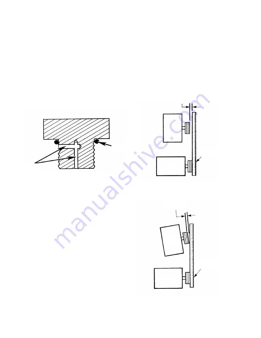
4.5 SHEAVE ALIGNMENT
Any degree of sheave misalignment will result in a
reduction of belt life. Misalignment of belt drive should
not exceed 1/16 in. (1.6 mm).
Parallel misalignment occurs when the drive and dri-
ven shafts are parallel, but the two sheaves lie in dif-
ferent planes (See Figure 4.5-1).
Angular misalignment occurs when the two shafts are
not parallel (See Figure 4.5-2).
FIGURE 4.3-1 FILL PLUG WITH VENT HOLE
FIGURE 4.5-1 PARALLEL MISALIGNMENT
FIGURE 4.5-2 ANGULAR MISALIGNMENT
VENT
HOLE
O-RING
AIREND
AIREND
MOTOR
MOTOR
1/16” MAX
1/16” MAX
STRAIGHTEDGE
STRAIGHTEDGE
Summary of Contents for EP 20-ESP
Page 35: ...33 6 0 REFERENCE DRAWINGS 6 1 ELECTRICAL SCHEMATIC FULL VOLTAGE 39884143 REV 01...
Page 36: ...34 6 2 ELECTRICAL SCHEMATIC STAR DELTA 39884150 REV 01...
Page 38: ...36 6 4 FOUNDATION PLAN TANK MOUNTED CONTINUED 39871975 REV 03...
Page 39: ...37 6 4 FOUNDATION PLAN TANK MOUNTED 39871975 REV 03...
Page 40: ...38 6 5 FOUNDATION PLAN BASE MOUNTED CONTINUED 39872835 REV 03...
Page 41: ...39 6 5 FOUNDATION PLAN BASE MOUNTED 39872835 REV 03...
Page 44: ...42 39876461 REV 02...
Page 46: ...44 39880844 REV 01...
Page 48: ...46 39872031 REV 01 SEE PIPING ASSEMBLY OPTIONS...
Page 52: ...50 39872023 REV 02 TO AFTERCOOLER TO AFTERCOOLER...
Page 57: ...55 DATE RUN TIME WORK DONE QTY UNIT WORK HOURS MEASURE BY 8 0 MAINTENANCE RECORD...
Page 58: ...56 DATE RUN TIME WORK DONE QTY UNIT WORK HOURS MEASURE BY MAINTENANCE RECORD...


