Ingersoll-Rand 4MUD4518A10N0A Installation, Operation And Maintenance Manual Download Page 21

21

Using the Wireless Remote Control

To change system configurations using the Wireless Remote Control, follow this procedure:

1.

Remove the batteries from the remote control, and re-insert them while pressing the Temp+ and 
Temp- buttons simultaneously (refer to 

Figure , p. 23

).

The first 2-digit segment of a 24-digit sequence will appear on the wireless remote control 
display, as shown:

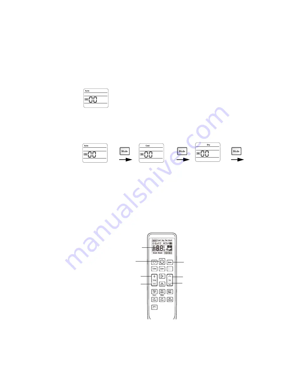
2. To advance to the next 2-digit segment, press the Mode button (

Figure , p. 23

). Continue 

pressing the Mode button until the two-digit segment appears that corresponds to the option 
setting or address setting you want to view or change. 

Each 2-digit segment is differentiated from the others by a combination of operation mode 
(Auto/Cool/Dry...) and ON/OFF icons, as shown below. (See “The 2-Digit Segments,” for more 
detailed information.)

Digits 2 and 3

Digits 4 and 5

Digits 6 and 8

...and so on, through 

digits 23 and 24.

Note:

Digits 1, 7, 13, and 19 do not appear and are not used for configuration.

3. To change the value of the left digit on the display, press the Fan down button. 

To change the value of the right digit on the display, press the Fan up button.

Note:

Values and their corresponding settings are listed in the following pages of this section 
of the manual.

4. To save the setting, press the Power button twice.

5. To restore the wireless remote control to normal operating mode, remove the batteries from 

the remote control. Then re-insert them.

Figure 3.

Mode button

Fan up

Fan down

Power button

2-digit segment

Note:

The wireless remote control may 

look different from the illustration, 

depending on the model.

Temp up

Temp down

Wireless Remote Control

Summary of Contents for 4MUD4518A10N0A

Page 1: ...alled adjusted or altered equipment by an unqualified person could result in death or serious injury When working on the equipment observe all precautions in the literature and on the tags stickers an...

Page 2: ...In addition some states or municipalities may have additional requirements that must also be adhered to for responsible management of refrigerants Know the applicable laws and follow them WARNING Prop...

Page 3: ...Insulation 17 Refrigerant Pipes 17 Drainage Hose 17 Wiring the Unit 18 Power Wiring 18 Communications Wiring 18 Configuration 20 Using the Technician Utilities Tool TUT 20 Using the Wireless Remote Co...

Page 4: ...Connection type 5 Flare Digit 7 8 Nominal capacity Btu h x 1 000 18 18 000 Btu h 36 36 000 Btu h 24 24 000 Btu h 42 42 000 Btu h 30 30 000 Btu h 48 48 000 Btu h Digit 9 Major development sequence A Fi...

Page 5: ...ely in the area to be cooled heated Sufficient clearance must be maintained around the unit Condensate must be managed correctly and safety away from the unit The unit should be installed in a way tha...

Page 6: ...20 6 18 157 Discharge side 5 4 2 1 3 12 60 320 9 92 252 5 20 132 2 99 76 5 67 144 3 94 x 2 7 87 200 Unit inch mm No Name Description 1 Liquid pipe connection 1 4 6 35 2 Gas pipe connection 18 MBH 1 2...

Page 7: ...sition 10 94 278 air outlet duct flange 3 94 100 6 22 158 5 39 137 4 80 122 4MUD4530A10N0A 4MUD4536A10N0A 4MUD4542A10N0A 4MUD4548A10N0A Unit inch mm No Name Description 1 Liquid pipe connection 3 8 9...

Page 8: ...ment could result in minor to moderate injury Unit width A W 3 94 100 B 19 7 500 0 78 20 0 78 20 Unit depth D Ceiling Unit Note If the unit is installed in a ceiling that does not have removable tiles...

Page 9: ...unting it Use the following guidelines D B C A Unit inch mm Indoor unit model Insulation A and B C and D 4MUD4518A10N0A 45 3 1150 x 12 6 320 18 9 480 x 12 6 320 4MUD4524A10N0A 4MUD4530A10N0A 47 2 1200...

Page 10: ...marks 2 Determine the appropriate type of suspension bolts and anchors according to the ceiling type Insert bolt anchors into existing ceiling supports A or construct a suitable support B A B Ceiling...

Page 11: ...it To purge the unit unscrew the pinch pipes from the ends of both gas and liquid refrigerant pipes Make sure all gas has escaped before connecting the piping Note To prevent dirt or foreign objects f...

Page 12: ...3002 28 psi 20 700 kPa Copper pipe for hydro sanitary applications is unsuitable For sizing and limits height difference line length maximum bends refrigerant charge and so on see the outdoor unit in...

Page 13: ...e end of the pipe that you flared should look like the end of a trumpet See examples of correctly and incorrectly flared pipes Inclined Damaged surface Uneven thickness Correct Cracked 8 Align the pip...

Page 14: ...dry nitrogen for pressurizing units Failure to follow these recommendations could result in death or serious injury or equipment or property only damage Do not exceed unit nameplate design pressures...

Page 15: ...cting the drain hose Drain hose port Drain hose port Drain hose Drain connection 8 Wrap the insulation supplied around the drain hose and clamp the connection as tightly as possible until you can see...

Page 16: ...f the installation requires more than three indoor units install the main air vent at the front of the indoor unit that is farthest from the main drain It may be necessary to install individual air ve...

Page 17: ...sulation tightly to pipe Do not wrap the gas and liquid refrigerant pipes together Avoid compressing the insulation as much as possible Be sure there are no cracks or deformities in the insulation at...

Page 18: ...unit will stop and an error code will be generated Connect the power cable to the auxiliary circuit breaker An all pole disconnection from the power supply must be incorporated in the field wiring 1...

Page 19: ...utdoor unit Communication cable Grounding Disconnect Circuit breaker Figure 2 Wiring terminals 1 L 2 N 1 2 V1 V2 F3 F4 F2 F1 1 L 2 N N L L1 L2 L1 L2 L1 L2 Indoor unit Main power cable Cable clamp Outd...

Page 20: ...Tool TUT follow this procedure 1 At the Indoor Unit Option Writer screen on the TUT select the desired option codes by referring to Table 1 p 23 2 Use the following table and notes to determine which...

Page 21: ...ol Dry and ON OFF icons as shown below See The 2 Digit Segments for more detailed information Digits 2 and 3 Digits 4 and 5 Digits 6 and 8 and so on through digits 23 and 24 Note Digits 1 7 13 and 19...

Page 22: ...igure 4 to set the wireless remote to Installation Option 1 Figure 4 Two digit segments in the 24 digit sequence Notes 1 Digits 1 7 13 and 19 shown in green are factory set and cannot be changed They...

Page 23: ...Factory set to 0 4 Enable only when a remote temperature sensor is used 0 Disabled 1 Enabled 5 Central control 0 Disabled 1 Enabled 6 RPM up 0 Disabled 1 Enabled N A 7 Factory set to 1 Cannot be chan...

Page 24: ...3 Not available Factory set to 0 24 Not available Factory set to 0 a Cassette type indoor units are set to Enabled 3 minute delay regardless of digit 8 setting b For heat pump systems the master indoo...

Page 25: ...runs in Heat mode frost may form due to the temperature difference between the unit and the outside air If this happens The unit stops heating The unit will operate automatically in Defrost mode for 1...

Page 26: ...7 C If the outdoor temperature drops to 32 F 0 C or below the heating capacity can be reduced depending on the temperature condition 4 F 20 C to 75 F 24 C 81 F 27 C or less Drying 0 F 18 C to 115 F 4...

Page 27: ...wipe the surface of the unit as needed If necessary use mild soap and water on a damp cloth Use a soft brush to remove dirt from the coil NOTICE Avoid equipment damage and risk of fire Avoid using be...

Page 28: ...internal damage Table 2 Maintenance schedule Description Monthly Every 4 months Once a year As needed Clean the air filter a a The described operations should be performed more frequently if the area...

Page 29: ...ion Verify the origin of the odor Operate the unit in Fan mode or open the windows to air out the room The unit makes a bubbling sound A bubbling sound may be heard when the refrigerant is circulating...

Page 30: ...ce 422 Errorof electronic expansion valveclose in the outdoor unit whenitisdetectedmore than once 601 Error of communication between the indoor unit and the wired remote controller Wired remote contro...

Page 31: ...ed by Company and or lack of proper maintenance as recommended by Company Company shall not be obligated to pay for the cost of lost refrigerant or lost product Company s obligations and liabilities u...

Page 32: ...portfolio of advanced controls and HVAC systems comprehensive building services and parts For more information visit www IRCO com The manufacturer has a policy of continuous product and product data...

Reviews: