


47
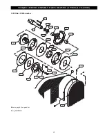
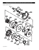
The following Reducer Assembly drawings are provided for reference only. The drawings are intended as a guide to the general internal
construction of the Reducer assemblies. Check the nameplate attached to the motor for appropriate Reducer assembly type. A typical
part number may be similar to R70DT90L4BMHR where the first letter represents the reducer type. For additional information and parts
contact your nearest distributor or Ingersoll-Rand Material Handling Office.
(Dwg. MHP0288)
‘S’ Type Reducer
‘R’ Type Reducer
(Dwg. MHP0309)
REDUCER ASSEMBLIES
Summary of Contents for 10000B20
Page 13: ...12 DRUM SWITCH CONNECTION DIAGRAMS Dwg MHP0201...
Page 14: ...13 230 Volt Single Phase 60 Hz Dwg MHP0271 WIRING DIAGRAM...
Page 15: ...14 WIRING DIAGRAMS Dwg MHP1086...
Page 16: ...15 Dwg MHP1087 WIRING DIAGRAM 208 575 Volt Three Phase 50 or 60 Hz 22 Amp and smaller...
Page 17: ...16 WIRING DIAGRAM Dwg MHP1088 208 575 Volt Three Phase 50 or 60 Hz 22 Amp and larger...