27
Limit Switch Assembly (optional feature)
Refer to Drawings MHP0263 and MHP0579.
Limit Switch Assemblies are custom mounted at the factory to
ensure proper alignment. Contact your local service center,
distributor or the factory before attempting to install a limit
switch kit on an existing winch. Request a copy of Dwg. 25308
for detailed installation instructions.
1,300 lb to 10,000 lb winches
1.
Install extension studs (70) on capscrews (14) on the side of
the frame opposite the roller chain.
2.
Install bracket (71) on extension studs (70) and secure in
position with lockwashers (13) and nuts (19).
3.
Tap pin (75) into the hole in the end of the drum until flush.
Install limit switch (72). The slot in the limit switch drive
shaft must be in line and engage with pin (75).
4.
Secure limit switch (72) to bracket (71) with screws (74)
and lockwashers (73).
15,000 lb to 25,000 lb winches
1.
Remove capscrews (41) and washers (42) from bearing
assembly. Install bracket (71) and reinstall capscrews and
washers. Do not tighten.
2.
Tap pin (75) into the hole in the end of the drum until flush.
Install limit switch (72). The slot in the limit switch drive
shaft must be in line and engage with pin (75).
3.
Secure limit switch (72) to bracket (71) with screws (74)
and lockwashers (73).
4.
Tighten capscrews (41).
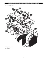
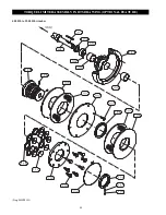
Torque Limiter Assembly
Refer to Drawings MHP0583 and MHP0854.
Ensure the clutch plate, motor sprocket, driving plate and
friction plates are free of oil, grease, dirt and rust prior to
assembly. The clutch plate should have a 125 micro-inch finish
in the bore and a 63 micro-inch finish on the area where the
friction plates rub in order to obtain maximum rated capacity
and optimum life from the Torque Limiter. Assemble the
following parts on the torque limiter clutch hub: friction plates
(107), bushing (109), clutch plate (102), driving plate (106),
spring(s) (110), load plate (112) and adjusting nut (115).
Testing
Operational Test
Prior to initial use, all new, altered or repaired winches shall be
tested to ensure proper operation.
1.
Operate winch for several minutes in both directions with
no load.
2.
Check operation of brake.
3.
Check operation of limit switches, and locking or safety
devices when provided.
4.
Check winch is firmly secured before beginning operation.
Refer to “INSTALLATION” section.
5.
Install guards and ensure warning labels are present and
legable.
Load Test
Prior to initial use, all new, extensively repaired, or altered
winches shall be load tested by or under the direction of a
person knowledgeable in test procedures and operation of the
winch, and a written report furnished confirming the rating of
the winch. Test winch to 110% of the rated line pull.
Summary of Contents for 10000B20
Page 13: ...12 DRUM SWITCH CONNECTION DIAGRAMS Dwg MHP0201...
Page 14: ...13 230 Volt Single Phase 60 Hz Dwg MHP0271 WIRING DIAGRAM...
Page 15: ...14 WIRING DIAGRAMS Dwg MHP1086...
Page 16: ...15 Dwg MHP1087 WIRING DIAGRAM 208 575 Volt Three Phase 50 or 60 Hz 22 Amp and smaller...
Page 17: ...16 WIRING DIAGRAM Dwg MHP1088 208 575 Volt Three Phase 50 or 60 Hz 22 Amp and larger...


