62
Chapter 4 - Connections
XtrapulsPac Installation Guide
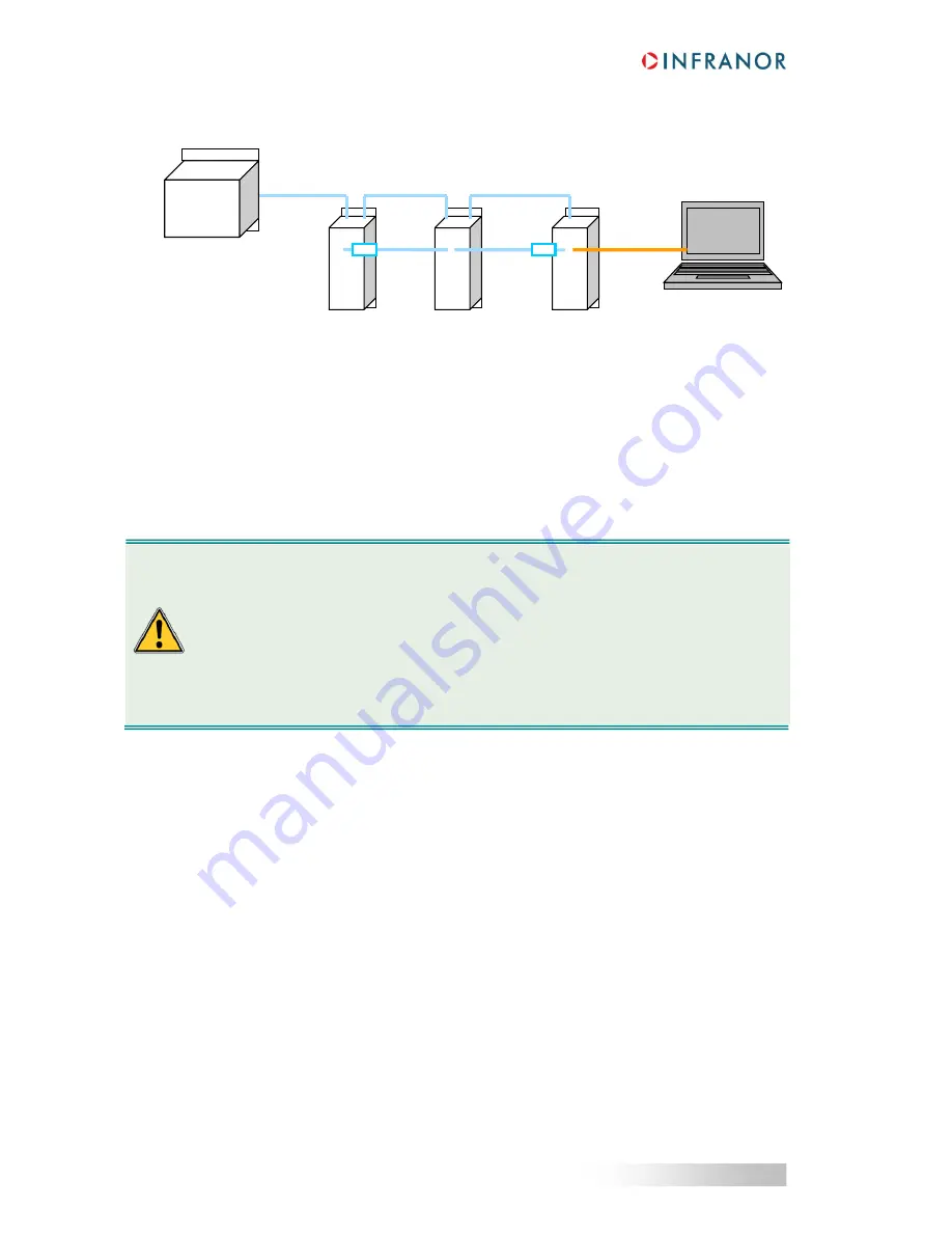
4.5.2.2 - XtrapulsPac drive in EtherCAT® configuration
In the EtherCAT® configuration, the RS232 and CAN communication is made via the SUB D 9 pins connector X5.
The multi-axis parameterization is then made according to the diagram above.
4.6 - WIRING INSTRUCTIONS
According to the EN61000.4-2-3-4-5 and EN55011 standards.
4.6.1 - Ground connection
The PE wire of the mains cable MUST be connected to the ground screw marked with the ground symbol on the
front of the drive.
Fastening torque of the ground screw: 0.77 Nm.
The reference potential must be the ground
: 10 mm² section or ground braid to the reference potential.
If there is a potential reference, e.g. a chassis or cabinet with low impedance between its various parts, it should
be used for connections to this potential which shall be itself grounded.
Reference potential loops (especially with the ground) are allowed
only
if these loops have a very low impedance
(< 0.1
). Any shield that is not used as a conductor can be connected at both ends under the condition to be
connected over 360° at both ends by means of metal links in order to ensure the shield continuity.
RS 232
Setup
monitoring
EtherCAT®
host controller
EtherCAT®
EtherCAT®
X6
X6
X6
X5
X7
X7
X5
X5
RT
RT
CAN bus
CAN bus
LEAKAGE CURRENT TO THE GROUND
The "Electronic Power Unit" equipment which includes the control, the drive, the motor and the
sensors, generates a leakage current to the ground higher than 10 mA continuous: the protection
conductor section must be
at least
10 mm² (Cu) or 16 mm² (Al).
This product may generate a leakage current with a DC component.
If a Residual Current Device is used, it should be:
- of type A in single-phase applications,
- of type B in three-phase applications.
The use of a 300 mA trip current is recommended.
RT = 120 Ohm terminal resistor connected between CAN-L and CAN-H lines


