background image


15 

EN 

Pleats 

 
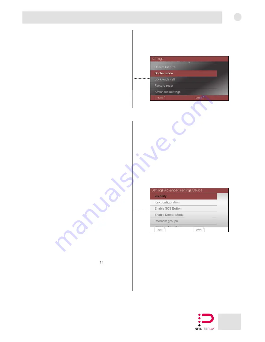
10-Doctor mode  

It is possible to activate or deactivate the doctor mode. 
If the doctor mode is active, when the video door entry system receives a 
call from the external entrance panel, it will automatically open the 
electric lock. 
The function must be previously set in the Advanced Settings-> Device-> 
Doctor Mode (13.1.4) section. 
 

11-End Call Lock Button 

It is possible to enable or disable the "end call lock button" function. If 
active, during the call on the entrance panel, pressing the electric lock 
open button, the lock will be opened and the call will be closed. 

 
12-Factory data reset 

It is possible to perform a factory reset, which will delete all data and 
configuration of the video door entry system. 
 

13-Advanced Settings 

Through the "advanced settings" It is possible to access the advanced 
settings of the video door entry system. 
To access the settings, it is necessary to enter the password. 

The default password is "000000". 

13.1-Device 

From the "device" section it is possible to act on the visibility of entrance 
panels, video door entry systems, switchboards and video door entry 
functions. 
Furthermore, it is possible to configure the programmable buttons of the 
PLEATS video door entry system. 

Note: To apply the changes select "Save configuration" at the end of the 
list. 

13.1.1-Visibility 

It is possible to select the devices to make visible to the PLEATS video 
door entry system. 
Then tick the desired devices and press "done". 

13.1.1.1-Functions 

It is possible to select the video door entry functions to make visible to 
the PLEATS video door entry system. 
Then tick the desired devices and press "done". 

13.1.1.2-Entrance panels 

It is possible to select the external entrance panels to make visible to the 
PLEATS video door entry system. 
Then tick the desired devices and press "done". 

13.1.1.3-Video door entry systems 

It is possible to select the video door entry systems to make visible to the 
PLEATS video door entry system. 
Then tick the desired devices and press "done". 

13.1.1.4-Switchboards 

It is possible to select the concierge stations to make visible to the PLEATS 
video door entry system. 
Then tick the desired devices and press "done". 

13.1.2-Buttons mapping 

It is possible to configure the programmable buttons, assigning them a 
function. 
To configure a button it is necessary to select it from the button list, and 
immediately after associate the desired function. 
Once programmed, the buttons can make calls, entrance panels self-
starts and use the video door entry system functions. 

13.1.3-SOS 

It is possible to configure the programmable button

, with the SOS 

function. 
In case of activation, the SOS function sends a request for help to the 
switchboard connected to the system. 

If this function is activated, the

 SOS


button will no longer be configurable 

with other types of functions. 
If there is no switchboard in the system, the function is useless. 


Summary of Contents for PLEATS Z4000

Page 1: ...Z4000 Installer manual ...

Page 2: ...urb 14 10 Doctor mode 15 11 End Call Lock Button 15 12 Factory data reset 15 13 Advanced Settings 15 13 1 Device 15 13 1 1 Visibility 15 13 1 1 1 Functions 15 13 1 1 2 Entrance panels 15 13 1 1 3 Video door entry systems 15 13 1 1 4 Switchboards 15 13 1 2 Buttons mapping 15 13 1 3 SOS 15 13 1 4 Doctor mode 16 13 1 5 Intercom Groups 16 13 1 6 Save configuration 16 13 2 System 16 13 2 1 System langu...

Page 3: ...on when the user gets near to it Through the backlit soft touch buttons it is possible to interface with the video door entry system Backlit buttons and proximity sensor are not available in the low cost version Z4000 L PLEATS Z4000 allows to make and receive intercom and SIP calls it allows to receive calls from external entrance panels and to self start them It is possible to exploit the video d...

Page 4: ...4 EN Pleats 1 2 Front view 1 3 Rear view Proximity sensor Colour LCD display Microphon Programmable touch buttons Handset Speaker Ethernet connector RJ11 connector Auxiliary connectors ...

Page 5: ...5 EN Pleats 1 4 Side view and bottom view Volume buttons Mini USB connector Reset button ...

Page 6: ...6 EN Pleats 1 5 Description of buttons 2 3 4 5 6 7 8 9 10 1 ...

Page 7: ...used for the light on video door entry system function 8 Call button Used to answer silence close a call 9 Volume button In the menus it is used for scrolling While typing to display additional characters 10 Volume button In the menus it is used for scrolling While typing to display additional characters Button combinations Button and button Activate Deactivate the do not disturb mode Button and b...

Page 8: ...lugs and two self tapping screws 2 Unified rectangular wall mounted box with 3 modules in vertical configuration mounting plate one M3 screw four self tapping screws and four wall plugs 3 Round wall mounted box diameter 60mm mounting plate two M3 screws two self tapping screws and two wall plugs 4 Corrugated pipe without wall mounted box mounting plate four self tapping screws and four wall plugs ...

Page 9: ... to the RJ11 connector on the back of the video door entry system Then place the cable as shown in figure 1 Note When installing the video door entry system on the mounting plate remember to pass the cable through the cable holder Figure 2 Handset cable connection Cable holder Handset support Video door entry system RJ11 connector 1 2 ...

Page 10: ...ox taking care to pass the cables through the cable hole 3 Insert the video door entry system on the hooks of the mounting plate 4 Slide the video door entry system down to lock it on the mounting plate Pass the handset cable through the cable clamp Installation Height from the ground 145 150cm Cable hole Hooks for PLEATS installation Mounting plate 1 2 3 4 Cable holders Cable holders ...

Page 11: ... configuration To remove the handset holder use a screwdriver to pry up the bottom of the handset holder To remove the video door entry system it is necessary to slide it upwards and then remove it from the support For the connection diagrams refer to the CONNECTION DIAGRAMS section located in the contents CAUTION The video door entry system must be located away from light and heat sources Install...

Page 12: ...V AC DC relay contact The two terminals marked CH are a normally open contact FP Auxiliary landing call button AL Generic alarm auxiliary button P Panic auxiliary button Ethernet connector Connector used for data traffic and POE power supply RJ11 connector Connector used to connect the handset 4 Maintenance Clean the product using a soft cloth do not pour water on the device and do not use any typ...

Page 13: ... connectors Tester for ethernet cables Procedure 1 Strip the cable about 10mm taking care not to damage the insulation of the individual cables 2 Sort the cables as shown in the figure and even them up cutting the excess 3 Insert the cables into the RJ45 connector Check that the order of the cables remains unchanged after inserting the connector 4 Crimp the cable using the appropriate clamp making...

Page 14: ...alls Ringtone for calls from entrance panels Intercom calls Ringtone for intercom calls Notification sounds Ringtone for notifications To set the desired ringtone it is necessary to select it from the list 5 2 Volume It is possible to change the ringtone volume and the call volume An indicator will be shown on which it is possible to act to adjust the volume Ringtone Speaker volume for ringtones C...

Page 15: ...devices to make visible to the PLEATS video door entry system Then tick the desired devices and press done 13 1 1 1 Functions It is possible to select the video door entry functions to make visible to the PLEATS video door entry system Then tick the desired devices and press done 13 1 1 2 Entrance panels It is possible to select the external entrance panels to make visible to the PLEATS video door...

Page 16: ...de Through this setting it is possible to activate the master mode Activating the master mode only the master devices will be visible i e those with Object ID that ends with 00 Example of master device 010000000100 13 2 5 Power supplies It is possible to activate the video door entry functions of the power supplies Z6001 Z60DT in the system Pressing Power Supplies will display the power supplies t...

Page 17: ...hone AUX3 AUX3 free PORTE RJ45 AL GND N GND GND GND INPUT GND INPUT S Lock return COM 1 COM 2 COM 3 USB IN4 PW PW Power 12V Relay additional chime CH2 USB M Relay additional chime Power Video door phone Entrance panel Video door phone CONNECTION DIAGRAMS 1 Single family video door entry system Composed of an external entrance panel a power supply and an internal video door entry system WIRING SPEC...

Page 18: ...AUX2 12Vcc 1A Lock Power Supply Z6001 RJ45 IN1 P2 AUX3 PORTE RJ45 GND N GND GND S Lock return COM 1 COM 2 COM 3 USB IN4 Video door phone 2 Entrance panel Video door phone 2 P CH1 FP RJ45 AL PW PW CH2 USB M 2 P CH1 FP RJ45 Panic Button Alarm INPUT GND Outdoor call button AL PW PW Power 12V Relay additional chime CH2 USB M Relay additional chime Power Panic Button Alarm INPUT GND Outdoor call button...

Page 19: ...G SPECIFICATIONS CLAMP CABLE MAX LENGTH CONNECTOR P1 P2 P3 P4 Eth CAT5 or higher 100 metres RJ45 S S 1 5mm2 100 metres IN1 2 3 4 1mm2 100 metres With 10W lock Entrance panel Video door phone 1 CAT5 CAT5 CAT5 RJ45 Video door phone 2 with internet connection HOME INTERNET 12Vcc 1A Lock 1 2 P CH1 FP AL PW PW CH2 USB M 2 P CH1 FP AL PW PW CH2 USB M FIREWALL Distributor Z600F Power Supply Z6001 Interne...

Page 20: ...CTOR P1 P2 P3 P4 Eth CAT5 or higher 100 metres RJ45 S S 1 5mm2 100 metres IN1 2 3 4 1mm2 100 metres With 10W lock Entrance panel CAT5 CAT5 RJ45 12Vcc 1A Lock CAT5 CAT5 Video door phone 1 2 P CH1 FP AL PW PW CH2 USB M 2 P CH1 FP AL PW PW CH2 USB M Video door phone Video door phone Distributor Z60DV Distributor Z60DV Distributor Z60DV Power Supply Z6001 Video door phone Internet of building Conducto...

Page 21: ... CLAMP CABLE MAX LENGTH CONNECTOR P1 P2 P3 P4 Eth CAT5 or higher 100 metres RJ45 S S 1 5mm2 100 metres IN1 2 3 4 1mm2 100 metres With 10W lock CAT5 CAT5 CAT5 Video door phone 12Vcc 1A Lock CONCIERGE INTERNET of building Entrance panel 12Vcc 1A Lock 1 1 2 P CH1 FP AL PW PW CH2 USB M Video door phone Distributor Z60DV Distributor Z60DV Power Supply Z6001 Distributor Z60DT ...

Page 22: ...e Video door phone Contact Push button Sensor 2 P CH1 FP RJ45 AL PW PW CH2 USB M 2 P CH1 FP RJ45 AL PW PW CH2 USB M 2 P CH1 FP RJ45 AL PW PW CH2 USB M ALLARM INPUT to concierge Power supply 12 Vdc Video door phone Panic Button Alarm INPUT GND Outdoor call button Power 12V Relay additional chime Relay additional chime Power Panic Button Alarm INPUT GND Outdoor call button Power 12V Relay additional...

Page 23: ... P3 P4 P5 IN2 Stair light IN3 IN2 S AUX1 AUX2 12Vcc 1A Lock AUX1 Stair light 2A 24Vdc AUX2 Driveway gate Power Supply Z6001 IN1 P2 AUX3 AUX3 free PORTE RJ45 GND N GND GND GND S Lock return COM 1 COM 2 COM 3 USB IN4 STAIRS LIGHT CONTOL P1 L P3 P4 P5 IN3 IN2 S AUX1 AUX2 12Vcc 1A Lock Power Supply Z6001 IN1 Lock release IN1 P2 AUX3 PORTE RJ45 GND N GND GND GND INPUT S COM 1 COM 2 COM 3 USB IN4 wire 1...

Page 24: ...24 EN Pleats Installer notes ...

Page 25: ...25 EN Pleats Installer notes ...

Page 26: ...voltage supplied by the distribution network Before carrying out maintenance operations disconnect the appliance from the mains power supply In case of failure or malfunction of the appliance turn off the power and contact the service centre Do not obstruct the ventilation openings or slots in the power supplies Directive 2012 19 EU WEEE RAEE The crossed out bin symbol indicates that the product m...

Page 27: ...InfinitePlay S r l Via Antonio Ferrero 9 35133 Padova PD ITALY Tel 049 706344 www infiniteplay com ENG 18901079 RL05 03 18 INFINITEPLAY ITALY ...

Reviews: