background image

User Manual

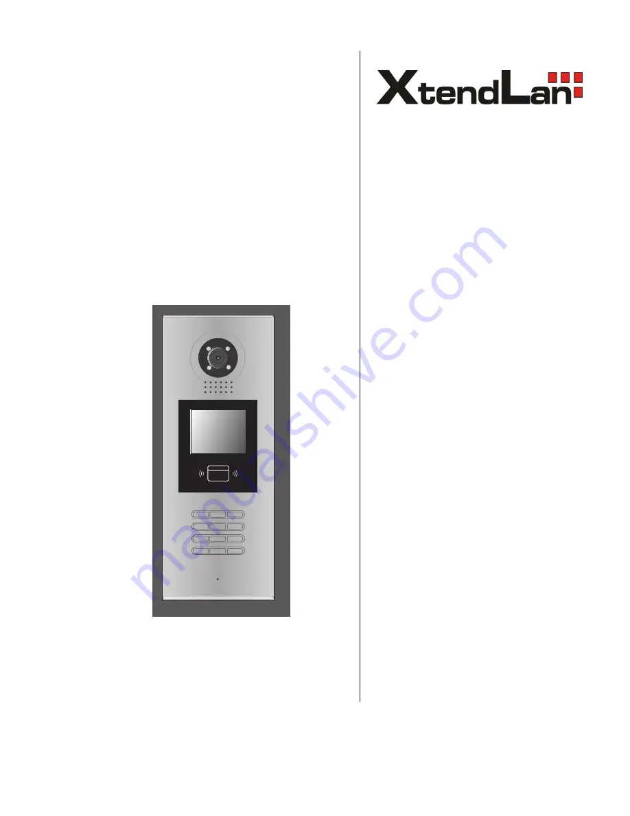
Door Station

Please read this manual carefully before using the product you purchase, and keep it well for future 

use.We reserve the right to modify the specification in this manual at any time without notice.

1

2

3

6

5

4

7

8

9

#

0

*

RF CARD

DPC-518ID

Summary of Contents for DPC-518ID

Page 1: ...se read this manual carefully before using the product you purchase and keep it well for future use We reserve the right to modify the specification in this manual at any time without notice 1 2 3 6 5...

Page 2: ...Parts and Functions 1 2 Terminal Descriptions 1 3 Door Station Mounting 2 4 Basic System Connection 3 5 Door Lock Connections 4 6 Door Station Configurations 6 7 Language and UI updating 11 8 Specifi...

Page 3: ...ut LK GND Power ground LK COM Common contact of the Relay NO Normally open contact of the Relay Can be set to be normally closed EB Exit button connection port Short EB EB to unlock EB Exit button con...

Page 4: ...to fix the metal box Attach the unit to the rainy cover correctlly Attach the baffle to protect the unit from droping The last view for all mounting The view for rainy cover after mounted Adjust the...

Page 5: ...basic system consists of Door station Distributor Monitor Power supply and lock 3 C5 F4 C5 F4 Connect to next C5 F4 T R CN LK T R J KMB JP LK EB EB N O LK LK 12V 1 2 3 12 V DC lock PS5 1 2 3 6 5 4 7 8...

Page 6: ...tion can only output 12Vdc power Any high power lock should use external power connection or it might cause damage to the door station The rated power of the lock must be less than 12Vdc 300mA when us...

Page 7: ...er Supply Mode When the electronic lock is over 12 Vdc additional power supply for the lock is needed The power supply for the lock must be less than 48Vdc 1 5A The Jumper must be removed when using e...

Page 8: ...y default Debug State menu is launched 9 0 0 8 Please Input Password 1 2 3 6 5 4 7 8 9 0 RF CARD D e b u g S t a t e 1 To o l s 0 R e d i a l 2 E x i t s About Debug Tools During working at Debug Stat...

Page 9: ...ge 1 2 Tone Select 03 3 Tone Volume 08 4 Unlock Code 1111 5 Display Mode 6 Clock 7 Setup Code 8 About 9 Default 3 Card Manage 1 Add Card 2 Delete By Card 3 Delete By M code 4 Cards Information 5 Forma...

Page 10: ...ed Mode 0 Card Memory To choose to use the memory of door station or that of C5 IPC when access cards are in use 0 Use memory of DS for access 1 Use C5 IPC for access 0 Doorplate Mode To choose the in...

Page 11: ...state can open the door at the same time If set to 0 unlock function is disabled Set to 1 unlock is enable Set to 2 unlock is enable and close at once Set to 3 unlock is enable and close in 5s 1 Ring...

Page 12: ...Time format if set to 0 time format is 24 hour standard If set to 1 time format is12 hour standard Setup Code To change the Program Code 88888888 About 1 Hardware version To show the Door Station incl...

Page 13: ...mation To show the amount of cards added To count how many times cards are swiped Format To delete all the cards and count information Table 4 Card Manage 7 Language and UI updating It s convenient fo...

Page 14: ...iring Cat5 Step 1 Insert the SD card which is contained config files into the SD card slot where is at the back of the door station Refer to the right diagram Step 2 If door station runs as Debug Stat...

Reviews: