User Guide
8 of 44
Revision 1.1
2021-03-21
EVAL-M3-302F User Guide
iMOTION™ Modular Application Design Kit
EVAL-M3-302F main features
4.1
Functional description
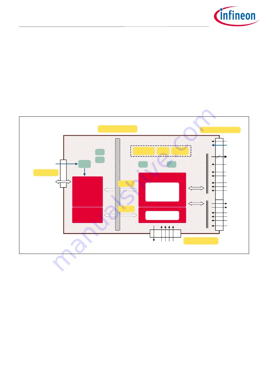
Figure 2 shows the block diagram of the EVAL-M3-302F. The IMC302A-F064 provides a built-in, closed loop and
sensorless control algorithm using the unique flexible Motion Control Engine (MCE) for permanent magnet
motors, and additionally a boost or totem pole power factor correction (PFC). The MCE™ consists of a collection
of control elements, motion peripherals, a dedicated motion control sequencer and internal memory to map
internal signal nodes. IMC302A-F064 also employs a unique single shunt current reconstruction circuit in addition
to a leg shunt current sensing circuit to eliminate additional analog/digital circuitry.
The integrated MCU is based on an Arm® Cortex® M0 core. It is internally connected to the MCE via a fast serial
port. The debug interface (SWD) is routed to the on-board debug interface via a galvanic isolation.
LED
LED
Status
PG out
M3 30 pin connector
15 V
3.3 V
PWM
U/V/W
6
GK
VDC
VTH
IU/ISS
IW
IV
IPFC
VAC+
VAC-
PFCG0
PFCG1
n.c.
iMOTION Controller
Motion Control
Engine
(MCE 2.0)
3.3 v
3.3 v AHALL 1/2
DHALL 1/2/3
ARM
®
Cortex
®
-M0
board specific pin headers
iMOTION Link
GPIO
UART
LDO
3.3 V
LED
LED
PWR
COM
VDD
5 V
SEGGER
J-Link
XMC4200
SWD
galvanic isolation
micro USB
hall connector
UART0
Figure 2
Block diagram of the EVAL-M3-302F


