


TC1796
Peripheral Units (Vol. 2 of 2)
Controller Area Network (MultiCAN) Controller
User’s Manual
22-18
V2.0, 2007-07
MultiCAN, V2.0
22.3
MultiCAN Kernel Functional Description
22.3.1
Module Structure
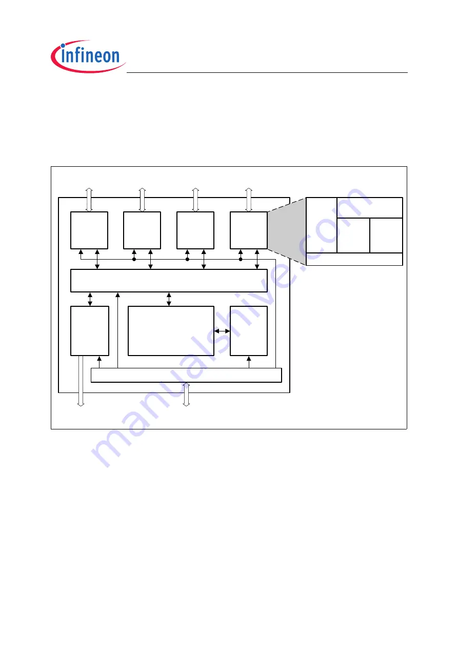
shows the general structure of the MultiCAN module.
Figure 22-7 MultiCAN Block Diagram
CAN Nodes
Each CAN node consists of several sub-units.
•
Bitstream Processor
The Bitstream Processor performs data, remote, error and overload frame
processing according to the ISO 11898 standard. This includes conversion between
the serial data stream and the input/output registers.
•
Bit Timing Unit
The Bit Timing Unit determines the length of a bit time and the location of the sample
point according to the user settings, taking into account propagation delays and
phase shift errors. The Bit Timing Unit also performs re-synchronization.
MCB05833
CAN Bus 0
Message Controller
CAN
Node 0
CAN Bus 1
CAN
Node 1
CAN Bus 2
CAN
Node 2
CAN Bus 3
List
Control
Logic
Message
RAM
Address Decoder
Interrupt
Control
Logic
CAN
Node 3
Bitstream
Processor
Bit
Timing
Unit
Error
Handling
Unit
Node
Control
Unit
Frame
Counter
Interrupt Control Unit
Bus Interface
Interrupt Control


