Delta Treatment Systems • 9125 Comar Drive, Walker, LA 70785 • 1-800-219-9183 • www.deltatreatment.com
9
INSTALLATION INSTRUCTIONS
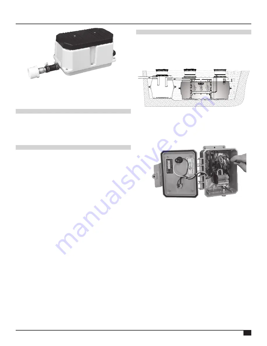
B. If using the linear blower (Thomas model LW250) attach
the 1-inch galvanized male adapter to the blower using
the supplied hose and clamps. Next attach the 2-inch
Schedule 40 PVC reducer to the male adapter, then
connect the PVC line to the reducer using PVC solvent.
7. Air Compressor Placement
Do not install the air pump(s) in a low-lying area where water
may accumulate. The air pump should be installed near the
control panel and within 100 ft. of the reactor tank. The air pump
can be installed outdoors or in a clean, well ventilated area, such
as a tool room, garage, etc.
8. Mounting Control Panel
Mount the control panel in a location such that the alarm can
be heard and be readily observed. The control panel must be
connected to a 20-amp maximum electrical source equipped
with a ground fault interrupter (GFI) circuit breaker. Install a
power disconnect switch to the panel that is operable and
available to a maintenance provider. The control panel must
be grounded. Connect the source ground wire to the ground
location in the panel. All electrical work shall be done according
to NEC and local code requirements.
A. Attach control panel to a suitable mounting surface. Use
appropriate screws for all four mounting holes on the
back of the enclosure.
B. The control panel contains a fuse or circuit breaker for
the air pump. An electrical malfunction in the air pump,
or wiring to the air pump, will cause the fuse or circuit
breaker to blow. The control panel also contains a
pressure switch and visual and audible alarms. Loss of
air pressure caused by air pump system malfunction, or
a high-water level in the treatment tank, will cause the
alarm to sound and light to illuminate.
C. Control panel is rated for outdoor service. However, do
not place it where it can be immersed in rising water or
where runoff water such as from a roof will pour onto
it. Do not mount it where it is subject to wetting from
sprinklers, hoses, etc.
D. Connect conduit. After the control panel is properly
mounted, connect conduit and install wiring as shown
on drawings bound herein (Schematics).
E. Connect the pressure air tubing to the 1/8” barb-fitting
in the air piping system. The air tubing should be
protected by conduit as shown on the drawing.
9. System Startup
Turn power on. Once the tank water level reaches the outlet tee,
turn power on to control panel. Air pump should start.
A. Set the high-level pressure switch.To set the high-level
pressure switch that detects high water level in the unit
bring the tank to operating water level with compressor
turned on. Using properly sized screwdriver turn high
level alarm adjustment screw clockwise until alarm
occurs. Then turn the screw counterclockwise until
alarm stops.
B. Check air piping joints for leakage using a soapy water
solution. Repair if necessary and then carefully backfill
air distribution piping and tanks.
C. Finish grade the site. Divert surface water away from
the system and install or plant ground cover to prevent
erosion.
D. Tank is ready to receive incoming sewage. No special
start-up procedures are required. The process is
naturally occurring and does not require any special
additives.
E. Replace and secure all tank access lids. Close up the
enclosure door on control panel and lock if necessary.
F. Spend time with your customer whenever possible.
Review operation instructions. Be sure that the
customer has a manual to keep. This saves valuable
time avoiding return visits.
G. Retain these instructions for future reference.
WARNING: CONTROL PANEL CONTAINS HIGH VOLTAGE
AND MUST BE INSTALLED AND SERVICED ONLY BY
QUALIFIED PERSONNEL
Figure 5


