


C-COM Satellite Systems Inc.
Page 17 of 164
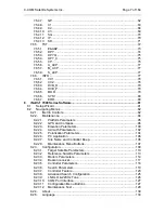
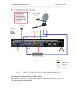
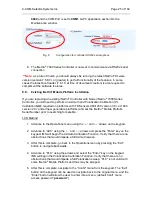
5.5.
System Diagram with Splitter
**Please Note
: Using a splitter is optional. If the user does not wish to power the LNB
from the Controller, a splitter must be used such that power is passed to the LNB from
the VSAT Modem (or alternate power source).
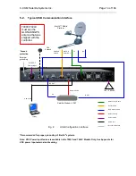
Fig. 7:
iNetVu
®
7000 Series Controller with Splitter Configuration
*Recommended for proper grounding of iNetVu
®
systems.
Note: VDC Power Input feature is available in the 7000C and 7024C Models Only. See Appendix for
VDC power input external cable wiring.
RX
GPS /Glonass
Antenna
iNetVu™ Mobile
Platform
MOTOR
CONTROL
TX
Satellite Modem / VSAT
!
100 - 260VAC
TX OUT
RX
SENSOR
CABLE
**If the splitter option is
used, ensure the LNB
Power is disabled in the
7000 Series Controller.
(See section 8.1.3.1 – “LNB
Power” for more detail)
RX IN
*
Ground
protection
External
grounding
connection
12/24 VDC
Power input
7000C/7024C
must use the
GLONASS/GPS
antenna that was
shipped with the
controller.
RG6 Coaxial Cable
Network Cable
Power Cable
Sensor Cable
Motor Control Cable
*
Ground Connection


