4
4. Technical Describtion:
Canopy construction:
The canopy of the Airtaxi² is made of nylon fabric by Dominico Tex Corp. and NCV Industries. This synthetically
manufactured fabric is woven with a reinforcing mesh to prevent tearing and increase tensile strength at the seams.
The coating makes the fabric water repellent, UV resistant and air impermeable.
The Airtaxi² consists of 52 cells. The wing tip (stabilizer) is pulled down and is integrated seamlessly into the canopy.
The canopy is ventilated through openings on the underside of the profile nose. Cross ventilation is provided by
precisely dimensioned holes (cross ports) in the profile rib.
Each main profile rib is suspended from a line connection. They are reinforced in the profile.
Tensioning straps are sewn in between the groups of main lines to regulate the sail tension.
Reinforcements are sewn into the profile nose to ensure high shape retention and stability.
A low-stretch tape is sewn into the leading and trailing edges, which provides a sophisticated tension distribution
across the canopy calculated by our construction software
Suspension System:
The lines of the Airtaxi² consist of polyester-coated and uncoated aramid and polyester-coated PES / Dyneema,
depending on the location. The strength of the individual lines varies from 70 to 500 daN depending on the location.
Depending on where the lines are installed, they are divided into upper lines (at the top of the canopy), middle lines,
main lines (or riser lines), stabilizer lines (at the wing end) and brake lines (at the top of the trailing edge) and main
brake lines (at the brake handle).
The lines are divided into A / B / C / D / E level and brake.
Within each level, 2 gallery lines are combined into one middle line. The 8 gallery lines of the E level are integrated in
the D middle lines. On the riser line level, 2 middle lines are grouped into a total of 6 riser lines per level and attached
to the corresponding risers.
The stabiliser lines are attached to the B-riser.
The brake or steering lines are combined into the main brake line according to the same principle.
The lines of each level are colored differently for easier control.
The riser of the Airtaxi² has 5 risers on each side.
The A-riser is divided into a main (A)- and a secondary riser (A'). In the A-riser are 2 main lines and A´-riser 1 main line
are attached.
In the B-riser 3 B main lines plus 1 stabilizer line are connected on each side.
The C riser holds 3 C main lines, the D riser 2 main lines. The upper lines of the E-level are joined to the D-level.
The main brake line is guided to the brake handle via a pulley on the D-riser.
The line connectors are made of stainless steel and are secured with a plastic insert against unintentional opening
and slipping of the lines.
There are no adjustable devices available.
The line arrangement is shown in the individual line plan.
Acceleration system:
The Airtaxi² only has a trimmer system in the D-riser. The riser does not have a foot accelerator.
The trimmer system lengthen the B, C and D risers and thereby reduces the angle of attack of the canopy - the trim
speed increases. In normal flight all risers have the same length (38,5 cm with line link). When the trimmer is
operated, the B-risers are extended by up to 1.5 cm, the C-risers by up to 3 cm and the D-risers by up to 6 cm. The A is
not changed.
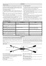
Functionality and handling:
The trimmers influence the take-off and flight behaviour! In the normal flight position, all risers have the same length,
brake
handle
pulley
brake line
brake handle
attachment
B
A
A’
C
D
B
A
A’
C
D
angle change
accelerator
trimmer
open
Coloured
marking
suspension
point harness
trimmer
closed
trim flight position
accelerated flight position
5
i.e. the trimmer is pulled down. To accelerate the paraglider, loosen the trimmer buckle. This extends the B/C/D riser,
reduces the angle of attack and increases the trim speed.
The adjustment buckle allows a stepless adjustment from "completely closed" to "completely open". Both trimmers
must always be adjusted symmetrically to the same position.
Varying the trimmer position can also be used to optimise the canopy's inflation behaviour depending on take-off
weight and wind conditions.
Overview risers:
5. Technical Data:
size
M - 41
Flat surface
m²
41,8
Flat span
m
14,88
Flat aspect ratio
A/R
5,3
Projected surface
m²
35,93
Projected span
m
11,79
Projected aspect ratio
A/R
3,87
Min take off weight
Kg
135
Max take off weight
Kg
235
V-Trim
Km/h
37
V-Max.
Km/h
54
LTF / EN Category
B
Changes of these data are possible!