background image

Golden Tee

®

 PGA TOUR

®

 Edition


Version 5/22


Page 28


© Copyright Incredible Technologies, Inc.  All Rights Reserved.  Unauthorized duplication is a violation of applicable law. 

All other marks are the properties of their respective owners. All rights reserved. Commercial. PN 900365060 


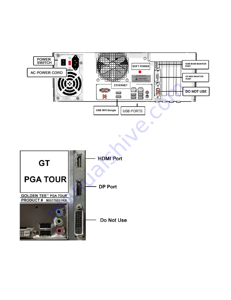
SYSTEM BOX CONNECTIONS  

Attach the AC Plug to the rear of the Pedestal cabinet and plug in to power source. Power ON Golden Tee PGA 
TOUR Edition. 
 

Titan System Box 


VIDEO CONNECTIONS FOR HDTV 

Golden Tee PGA TOUR Edition only supports 4K resolution.  Do not attempt to connect a monitor with less than 
4K resolution to the PGA TOUR Edition.  
 

Main Monitor HDMI Connection 

Connect the HDMI cable (supplied) to the 
HDMI Port on the Titan system box 
indicated as HDMI Port. 

DP Cable 

The DP Cable is already connected from 
the Mini Monitor to the DP Port on the 
Titan system box. If it becomes detached, 
make sure to reconnect the cable. 


Summary of Contents for Golden Tee PGA TOUR

Page 1: ...ly Mounting Brackets 12 3B Tubing Sub Assembly Upper Mounting Brackets 13 3C Attach Sub Assembly to Assembly Extensions 14 3D Sub Assembly Lower Brace 15 4A Marquee Shroud Front 16 4B Marquee Shroud Rear 17 5 Cable Feeds 18 6A Monitor Hanging Brackets 19 6B Monitor Mount Plate Standard 20 6B Monitor Mount Plate Alternate 21 6B Monitor Mount Plate Long 22 6C Hang Monitor 23 7 Side Panel Assembly 24...

Page 2: ... The VESA bracketing is universal and should work with all major television brands MAKE SURE YOUR HDTV IS 55 and 4K Shipped inside a plastic parts bag attached to the front of the cabinet 1 AC Power Cord for Pedestal Cabinet 10 Feet 1 HDMI Cable 15 Feet LEG LEVELER ADJUSTMENT Once your game is in position at the location it is necessary to adjust the leg levelers The leg levelers will help stabili...

Page 3: ...ds begin on the date of purchase from Incredible Technologies Inc There is a minimum 75 00 service charge for all non warranty repairs or returns For all servicing return to Incredible Technologies Inc ANY non factory repair or attempted repair voids warranty RETURN MERCHANDISE AUTHORIZATION All returned merchandise must have a Return Merchandise Authorization RMA number marked clearly on the outs...

Page 4: ...If the provided plug does not fit into your outlet consult an electrician for replacement of the obsolete outlet Protect the power cord from being walked on or pinched particularly at plugs convenience receptacles and the point where they exit from the apparatus Only use attachments accessories specified by the manufacturer Unplug this apparatus during lightning storms or when unused for long peri...

Page 5: ...ubstitute cords may not provide adequate fault protection Only use the power cord supplied with this product or an Incredible Technologies Inc authorized replacement The mains plug or an appliance coupler must remain readily operable Use of unauthorized parts or making any unauthorized modifications will void the warranty and may result in the game operating in an unsafe or incorrect manner This P...

Page 6: ...ks are the properties of their respective owners All rights reserved Commercial PN 900365060 PROFESSIONAL STAND INSTALL GUIDE The Professional Stand makes your Golden Tee PGA TOUR Edition rise above the competition It has been designed to be quickly assembled with minimal tools An adjustable wrench and a Phillips head screwdriver will be helpful to tighten the nuts and screws ...

Page 7: ...ount the bolts screws and washers listed here to make sure they are all included For a complete list of all parts see Appendix B Replacement Part Numbers Professional Stand Hardware Parts List Item Number Part Number Item Description Total Item Quantity 14 775000310 1 4 20 CONNECTOR BOLT BLACK 9 15 780000115 8 32 HEX PHILLIPS SCREW ZINC 18 16 780000751 5 16 18 PHILLIPS PAN SCREW ZINC 5 17 78500008...

Page 8: ...included for proper assembly Each part has an Item Number matching the circled number on the diagrams In each step the Item Number is listed after the item in italics Item Number Part Number Item Description Item Quantity 3 752365024 TUBING SUPPORT 2 1 Slide each Tubing Support Item 3 into the square shaped slots on the lower left and right sides on the rear of the Pedestal Cabinet The rear of the...

Page 9: ... 2 18 785000700 1 4 20 ACORN HEX NUT BLACK 4 19 790000030 1 4 FLAT WASHER ZINC 4 1 Slide 1 Tubing Extension Item 2 into each Tubing Support Make sure the OVAL CABLE PASS THROUGHS of the Tubing Extensions FACE INWARD See Pedestal Rear Side View diagram 2 Fasten 2 Zinc Washers Item 19 and 2 Acorn Hex Nuts Item 18 on the OUTER SIDE ONLY of each Tubing Extension OVAL CABLE PASS THROUGHS ON TUBING EXTE...

Page 10: ...000310 20 CONNECTOR BOLT BLACK 4 NOTE You will have a 4 hole Monitor Stand Brace or a 6 hole Monitor Stand Brace The 4 hole Monitor Stand Brace will need two extra Offset Brackets later in the procedure 6B Monitor Mount Plate 1 Attach 4 20 Connector Bolts Item 14 LOOSELY to the two holes at the top of each Tubing Extension Leave at least a 1 8 gap 2 Hang Monitor Stand Brace Item 11 on the Bolts ma...

Page 11: ...the Tubing Assembly already attached to the Pedestal The first step is to attach Mounting Brackets to the Tubing Assembly to hold the Sub Assembly in place In the diagram below look closely at Items 9 and 10 They look similar but they have different purposes The 4 Mounting Brackets Item 9 that attach to the Assembly hold the Sub Assembly in place The 2 Upper Mounting Brackets Item 10 attach to the...

Page 12: ...BLACK 4 14 775000310 1 4 20 CONNECTOR BOLT BLACK 2 1 Slide 2 Mounting Brackets Upper Position Item 9 into the hole above the Oval Cable Pass Throughs in each Tubing Extension Attach with 2 Connector Bolts Item 14 See Mounting Brackets Upper Position diagram 2 Fasten 2 Mounting Brackets Item 9 to the inside of the Tubing Extensions where they attach to the Tubing Supports using 2 Acorn Hex Nuts Ite...

Page 13: ...Quantity 4 900365065 TUBING SUB ASSEMBLY 1 10 752365039 UPPER MOUNTING BRACKET 2 18 785000700 1 4 20 ACORN HEX NUT BLACK 2 1 Slide the PEM on the S shaped Upper Mounting Bracket Item 10 through the Sub Assembly Item 4 Use second pre drilled hole from top See Upper Mounting Brackets diagram 2 Do the same on the opposite support Secure with 2 Acorn Hex Nuts Item 18 one on each side UPPER MOUNTING BR...

Page 14: ...ion Item Quantity 4 900365065 TUBING SUB ASSEMBLY 1 18 785000700 1 4 20 ACORN HEX NUT BLACK 4 1 Slide the Tubing Sub Assembly onto the PEMs of the Mounting Brackets already attached to the Assembly Extensions 3A Tubing Sub Assembly Mounting Brackets 2 Secure with 4 Acorn Hex Nuts Item 18 two on each side Sub Assembly to Tubing Assembly Extensions Attach Sub Assembly to Tubing Assembly Extensions w...

Page 15: ...y 4 900365065 TUBING SUB ASSEMBLY 1 15 780000115 8 32 HEX PHILLIPS SCREW ZINC 2 12 752365049 LOWER BRACE 1 1 Place Lower Brace Item 12 over the brackets on the rear of the Pedestal Cabinet and Base Support Assembly The Lower Brace should be snug and the holes aligned See Lower Brace diagram 2 Insert 2 Hex Phillips Screws Item 15 through the holes on each end of the Lower Brace and tighten 3 Adjust...

Page 16: ...90000075 8 FLAT WASHER BLACK 4 17 785000085 8 32 HEX KEPS NUT 4 1 Make sure the PGA TOUR Marquee Item 24 is on the front side of the PGA Monitor Shroud Item 27 2 Slide the Marquee onto the PEM studs inside the top of the Monitor Shroud 3 Fasten the Marquee to the Shroud using 4 8 Flat Washers Item 20 and 4 8 32 Hex Keps Nuts Item 17 on each of the four PEMs across the top of the Monitor Shroud See...

Page 17: ...rties of their respective owners All rights reserved Commercial PN 900365060 4B MARQUEE SHROUD REAR Item Number Part Number Item Description Item Quantity 15 780000115 8 32 HEX PHILLIPS SCREW ZINC 2 1 On the rear of the Shroud use 2 8 32 Hex Phillips Screws Item 15 to attach the Shroud to the Upper Mounting Brackets Item 10 See Marquee and Shroud Rear View diagram Marquee and Shroud Rear View ...

Page 18: ...ES SO IT IS EASIER TO FEED THEM THROUGH THE TUBING 1 On the left side facing Marquee front feed the 12V Cable through the oval cable pass through and into the cabinet Inside the cabinet connect the 4 pin side of the 12V connector to the yellow and black wire harness labeled Marquee 12V 2 On the right side facing Marquee front feed the 15 HDMI Cable through the oval cable pass through and into the ...

Page 19: ...CKETS 1 NOTE You will have one of the following Kits Standard Mounting Dream Kit Alternate Mounting Dream Kit or Long Mounting Dream Kit MONITOR MOUNTING 3 STEP INSTALLATION A ATTACH HANGING BRACKETS TO MONITOR B ATTACH MOUNT PLATE TO SHROUD C HANG MONITOR ON MOUNT PLATE Locate the four threaded holes on the back of the 55 monitor Using the bolts in pouch C attach 2 Hanging Brackets to the rear of...

Page 20: ...UNT PLATE STANDARD Item Number Part Number Item Description Item Quantity 22 795368001 STANDARD MOUNTING DREAM KIT MOUNT PLATE 1 16 780000751 5 16 18 PHILLIPS PAN SCREW ZINC BLACK 4 1 Hold the Mount Plate over the middle cut out on the front of the shroud Align the Monitor Mount so the four pre drilled holes in the Shroud align with the four outside edge openings on the Mount See diagram 2 Using 4...

Page 21: ...OLE MONITOR STAND BRACE 1 Hold Mount Plate A over the middle cut out on the front of the shroud Align Mount Plate A so the four pre drilled holes in the Shroud align with the four outside edge openings on the Mount See diagram below 2 Using 4 5 16 18 Phillips Zinc Pan Screws Item 16 attach Mount Plate A to the front of the Shroud Offset Bracket 3 Using 1 5 16 18 Phillips Zinc Pan Screw Item 16 to ...

Page 22: ...CE 1 Attach two sides of Mount Plate L Hold Mount Plate L over the middle cut out on the front of the shroud Align the Monitor Mount so the four pre drilled holes in the Shroud align with the four outside edge openings on the Mount See diagram 2 Using 4 5 16 18 Phillips Zinc Pan Screws Item 16 attach Mount Plate L to the front of the Shroud Offset Bracket 5 Using 1 5 16 18 Phillips Zinc Pan Screw ...

Page 23: ...t carefully lift the monitor into position and hang the monitor on the Mount Plate Do not lock the quick release spring clips until the monitor has been evenly centered against the shroud All sides should be even With the spring clips unattached the monitor will swing out making it easy to insert the HDMI Cable into the HDMI Input on the back of the monitor Connect the AC Power cable from HDTV to ...

Page 24: ...26 845365005 SIDE PANEL R 1 5 752365029 PANEL MOUNTING BRACKET 4 15 780000115 8 32 HEX PHILLIPS SCREW ZINC 8 1 Locate 2 Side Panels Items 25 L and 26 R 4 and 8 8 32 Hex Phillips Screws Item 15 2 Using four 8 32 Hex Phillips Screws attach the Panel Mounting Brackets Item 5 to the pre drilled holes on the inside of the left Side Panel Item 25 See Side Panel Mounting Left diagram Repeat on the right ...

Page 25: ...rties of their respective owners All rights reserved Commercial PN 900365060 8 CENTER COVER ASSEMBLY Item Number Part Number Item Description Item Quantity 1 750365009 CENTER COVER 1 7 752365031 CENTER COVER MOUNTING BRACKET 4 17 785000085 8 32 HEX KEPS NUT 2 1 Use the 8 32 Hex KEPS Nuts Item 17 to attach the Center Cover Mounting Bracket Item 7 to the top of the Center Cover See diagram below ...

Page 26: ...heir respective owners All rights reserved Commercial PN 900365060 9 CENTER COVER POSITIONING 1 Set the Center Cover Assembly in place so that the bottom edges are touching the Tubing Extensions and the back wall of the Pedestal Cabinet 2 Use slight pressure to bend the Cover and allow the pins to pop into the hole in the bottom of the Shroud See diagram THE ROUGH SIDE OF CENTER COVER FACES THE PE...

Page 27: ...orized duplication is a violation of applicable law All other marks are the properties of their respective owners All rights reserved Commercial PN 900365060 10 CONTROL PANEL IMPORTANT IT IS IMPORTANT TO REMOVE THE PROTECTIVE COATING ON THE CONTROL PANEL FAILURE TO REMOVE THE COATING WILL INHIBIT PROPER GAME PLAY ...

Page 28: ...binet and plug in to power source Power ON Golden Tee PGA TOUR Edition Titan System Box VIDEO CONNECTIONS FOR HDTV Golden Tee PGA TOUR Edition only supports 4K resolution Do not attempt to connect a monitor with less than 4K resolution to the PGA TOUR Edition Main Monitor HDMI Connection Connect the HDMI cable supplied to the HDMI Port on the Titan system box indicated as HDMI Port DP Cable The DP...

Page 29: ...external electrostatic air filter This filter is held in place by a metal bracket attached to the system box The filter prevents debris from entering the system box and damaging the electronic components A clogged filter will impede airflow thus building up unwanted heat which can cause damage to your hardware Be sure to check this filter at least once a month Remove the filter by sliding it out o...

Reviews: