


Download the driver port DCCD and the software on a laptop or a tablet running
Windows. Check the wire connections carefully. Turn on the ignition to make sure
the controller is connected.
Start the car. Connect the USB cable from the controller to the computer. Run
the program.
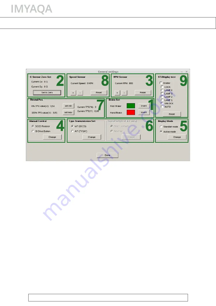
Click the "General settings" tab:
1. Check and adjust the hand and foot brakes: when the hand or the foot brake
is activated, the red light in “Brake Set” is on and the green light is on when the
brake is not activated. If it is not so - change the color by clicking “invent“.
2. Place the car on a horizontal surface and reset the G-Sensor by pressing the
"Set to Zero" button.
3. Compare the current engine speed with the speed displayed by the controller.
If there are discrepancies, adjust the "+" and "- "buttons.
4. Select the type of control in the manual mode: for the Si-Drive panel – "Si-Drive
Button", for the AUTO button and the wheel – "DCCD Resistor".
5. Select the display mode: the standard mode shows which mode or map is
active, and the active mode displays the current level of the lock.
6. Select the transmission type: manual or automatic. If it is necessary, invert the
solenoid control signal.
7. Set the minimum and maximum throttle position: when the throttle pedal is
not pressed, press "set min" and when the throttle pedal is fully depressed, press
"set max". Check the setting result, in "current TPS (%)".
8. Dial the speed and compare the current speed, with the speed displayed by
the controller. When diverging, adjust the "+" and "- "buttons.
9. If you connect an STI dashboard with a DCCD track, you can control the
operation with "STI Display test".
To check the setting result, press "Show log" and start moving.
BASIC SETTING
SETTING
,
page 1
If you have any questions, please write to


