Impax IM-MMA140 Instruction Manual Download Page 16

15

OPERATION

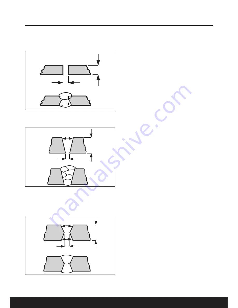
When welding material up to 7mm in thickness
place the pieces 2-3mm apart, run the welding
bead along the join. A second bead can go
along the underside for extra strength (Fig.10).

When welding material from 7mm to 30mm thick
prepare the material as shown in Fig.11 filling up
the space with several layers of weld.

When welding together material over 30mm in
thickness prepare the material as shown in
Fig.12 filling up the space with several layers of
weld, welding each side in turn with each
welding pass.

Disconnect the Welding Power Supply from the
mains supply before changing or removing
electrodes. Use pliers to remove used
electrodes from the electrode holder or to move
the welded pieces.

The Manual Metal Arc Process

When an arc is struck between the metal rod
(electrode) and the workpiece, both the rod and
workpiece surface melt to form a weld pool.
Simultaneous melting of the flux coating on the
rod will form gas and slag which protects the
weld pool from the surrounding atmosphere. The
slag will solidify and cool and must be chipped
off the weld bead once the weld run is complete
(or before the next weld pass is deposited).

The process allows only short lengths of weld to
be produced before a new electrode needs to
be inserted in the holder. Weld penetration is low
and the quality of the weld deposit is highly
dependent on the skill of the welder.

Types of Flux/Electrodes

Arc stability, depth of penetration, metal
deposition rate and positional capability are
greatly influenced by the chemical composition
of the flux coating on the electrode. Electrodes
can be divided into three main groups:

• Cellulosic

• Rutile

• Basic

Cellulosic electrodes

contain a high proportion

of cellulose in the coating and are characterised
by a deeply penetrating arc and a rapid burn-off
rate giving high welding speeds. Weld deposit
can be coarse and with fluid slag, deslagging
can be difficult. These electrodes are easy to
use in any position and are noted for their use in
the stovepipe (vertical down position) welding
technique.

Features:

•   Deep penetration in all positions 

•  Suitability for vertical down welding 

•  Reasonably good mechanical properties 

•  High level of hydrogen generated - risk of

cracking in the heat affected zone 

Fig 10                                             

7mm

2-3mm

Fig 11                                              

>30mm

60º

2-3mm

1

2

4

3

5

6

Fig 12                                              

>30mm

60º

2-3mm

Summary of Contents for IM-MMA140

Page 1: ...cumentation holder The technical documentation required to demonstrate that the product meets the requirements of directive has been compiled and is available for inspection by the relevant enforcemen...

Page 2: ...Always Read Instruction Manual Retain for Future Reference IM MMA140 140A MMA WELDER...

Page 3: ...adequately packed to prevent transit damage and must be accompanied with a brief description of the fault and a copy of the receipt or other proof of purchase The manufacturer shall not be liable for...

Page 4: ...e cables above below and adjacent to the welding equipment b radio and television transmitters and receivers c computer and other control equipment d safety critical equipment e g guarding of industri...

Page 5: ...ent With Output On Off Control Contactor Welding power sources for use with the gas metal arc welding gas tungsten arc welding and similar processes normally are equipped with devices that permit on o...

Page 6: ...ned space only while it is being ventilated and if necessary while wearing an air supplied respirator Vapours from chlorinated solvents can be decomposed by the heat of the arc or flame to form PHOSGE...

Page 7: ...ombustibles at least 10M away out of reach of sparks and heat or protect against ignition with suitable and snug fitting fire resistant covers or shields Walls ceilings and floor near work should be p...

Page 8: ...ses danger of explosion or on materials cleaned with chlorinated solvents or on varnished surfaces danger of toxic fumes Remove all flammable materials from the work area Ensure there is adequate fire...

Page 9: ...ate sparks which may ignite the dust or fumes c Keep children and bystanders away while operating a power tool Distractions can cause you to lose control 2 Electrical Safety a Power tool plugs must ma...

Page 10: ...tools Such preventive safety measures reduce the risk of starting the power tool accidentally d Store idle power tools out of the reach of children and do not allow persons unfamiliar with the power...

Page 11: ...acement fuse covers can be obtained from your local dealer or most electrical stockists Fuse Rating The fuse in the plug must be replaced with one of the same rating 13 amps and this replacement must...

Page 12: ...cator 13 Earth clamp attachment point 14 Electrode holder attachment point Technical specification Input power 230 240V 50Hz Phase 1 Rated input current 19 5A Fuse 16A Rated no load voltage 85V DC Rat...

Page 13: ...sk To assemble the mask bend in the top and side flaps Fig 1 and clip into place then attach the handle and mask glass shield as shown in Fig 2 Insert the clear glass panel first followed by the dark...

Page 14: ...LITY OF ANY WELDED JOINT IS DEPENDANT ONTHE PREPARATION OFTHE JOINTTHE SELECTION OFTHE CORRECT ELECTRODE ANDTHE SKILL AND EXPERIENCE OFTHE WELDER Ensure the Welding Power Supply is disconnected from t...

Page 15: ...piece must be 20 30 Fig 9 Do not hit the electrode on the workpiece as this may damage the electrode Withdraw with a clean movement at the end of the welding run Note This is the most difficult aspect...

Page 16: ...hipped off the weld bead once the weld run is complete or before the next weld pass is deposited The process allows only short lengths of weld to be produced before a new electrode needs to be inserte...

Page 17: ...s high as 130 to 140 can be achieved for rutile and basic electrodes without marked deterioration of the arcing characteristics but the arc tends to be less forceful which reduces bead penetration Car...

Page 18: ...t circuits Periodically clean the inside of the welder with compressed air ensuring you wear a mask during the operation Important Always disconnect from the electrical supply before servicing or clea...

Page 19: ...n the weld area prior to welding Weld current interrupted Thermal trip has operated Allow the welder to cool down Porous weld Rusty or dirty joints Clean the weld area prior to welding Irregular weld...

Page 20: ...l legislation FOR BUSINESS USERS INTHE EUROPEAN UNION If you wish to discard electrical and electronic equipment please contact your dealer or supplier for further information Information on Disposal...

Page 21: ...des 50Hz Nominal mains frequency Diameter of electrodes U0 No load voltage A V to A V Range of output X Duty cycle I2 Conventional welding current U2 Conventional load voltage U1 Mains voltage I1 max...

Page 22: ...21 NOTES...

Page 23: ...22 NOTES...

Page 24: ...23 NOTES...

Reviews: